1.1 Technical Specifications
1.1.1 Power Specifications
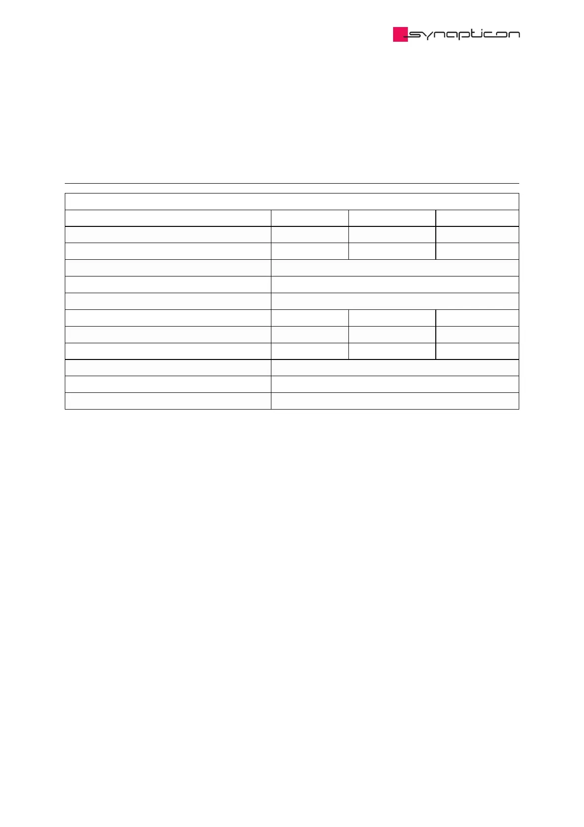
Power Specifications
Node Size Node 400 Node 1000 Node 2000
Maximum Peak Output Power 415 W 1,040 W 2,080 W
Maximum Continuous Output Power * 415 W 1,040 W 1,200 W
Rated Supply Voltage ** 12-48 V DC
Maximum Supply Voltage ** 60 V DC
Minimum Supply Voltage ** 8 V DC
Maximum Input Current DC 9.6 A DC 24 A DC 48 A DC
Maximum Phase Current RMS 13.2 A RMS 33 A RMS 66 A RMS
Maximum Continuous Phase Current RMS * 13.2 A RMS 33 A RMS 36 A RMS
Efficiency (at Maximum Power) 98 %
Standby Power Consumption 0.4 W
Brake control power output 0-48 V PWM Phase D ***
* These values can be achieved with a motor that is typical for robotic applications, reaching its
maximum power at 60% of its RPM maximum.
This case is used as a realistic assumption to specify the datasheet value for power. Beyond that, the
servo drive itself is able to provide higher power, as it is able to drive its maximum voltage and its
maximum current at the same time.
In reality, no motor can consume both maximum values at the same time, so there is no operating point
of the overall system (motor + drive) that would actually use the theoretical maximum power of the drive.
As the calculation bases on a reference motor, there are setups with large motors that are able to even
exceed the values shown here.
The maximum continuous output power and phase currents are highly dependent on the cooling
situation. Please refer to our Thermal mounting considerations for details.
** The operating voltage is 12-48 V DC. The maximum supply voltage is only for buffering peaks when
braking. The minimum voltage is for configuration purposes only. Please refer to our power supply
instructions for details.
*** This is a fourth phase that can also be used for other purposes (see Manually controlling phase D
voltage) it has a maximum current of 10 A.