1.5.6 Wiring the safety inputs
Attention
Attention
For SIL 3, PL e, cat.3 it is required to send test pulses from the PLC to the output or to ensure fault
For SIL 3, PL e, cat.3 it is required to send test pulses from the PLC to the output or to ensure fault
exclusion for wiring “Short circuit between any two conductors” according to ISO 13849-2:2012
exclusion for wiring “Short circuit between any two conductors” according to ISO 13849-2:2012
between signals STO-SBC 1 and STO-SBC 2
between signals STO-SBC 1 and STO-SBC 2
permanently connected (fixed) and protected against external damage, e.g. by cable ducting,
permanently connected (fixed) and protected against external damage, e.g. by cable ducting,
armouring, OR
armouring, OR
separate multicore cables, OR
separate multicore cables, OR
within an electrical enclosure, OR
within an electrical enclosure, OR
individually shielded with earth connection.
individually shielded with earth connection.
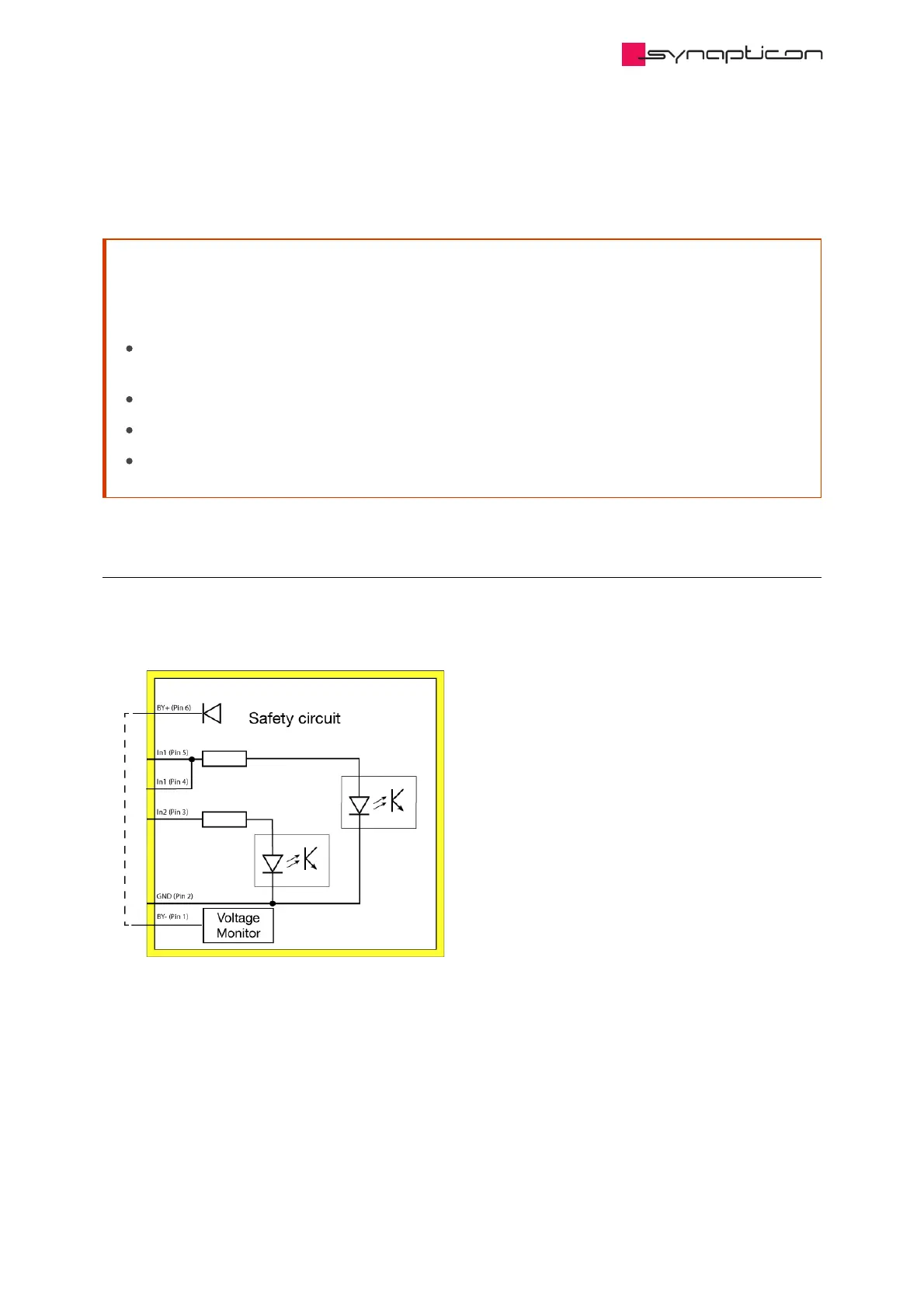
1.5.6.1 Disabling the safety functions
When the safety functions are not used, it is necessary to bypass the safety module. To do so, please
connect pins 1 and 6 of the safety module.