1.5.9.2.2 Wiring
Note
Note
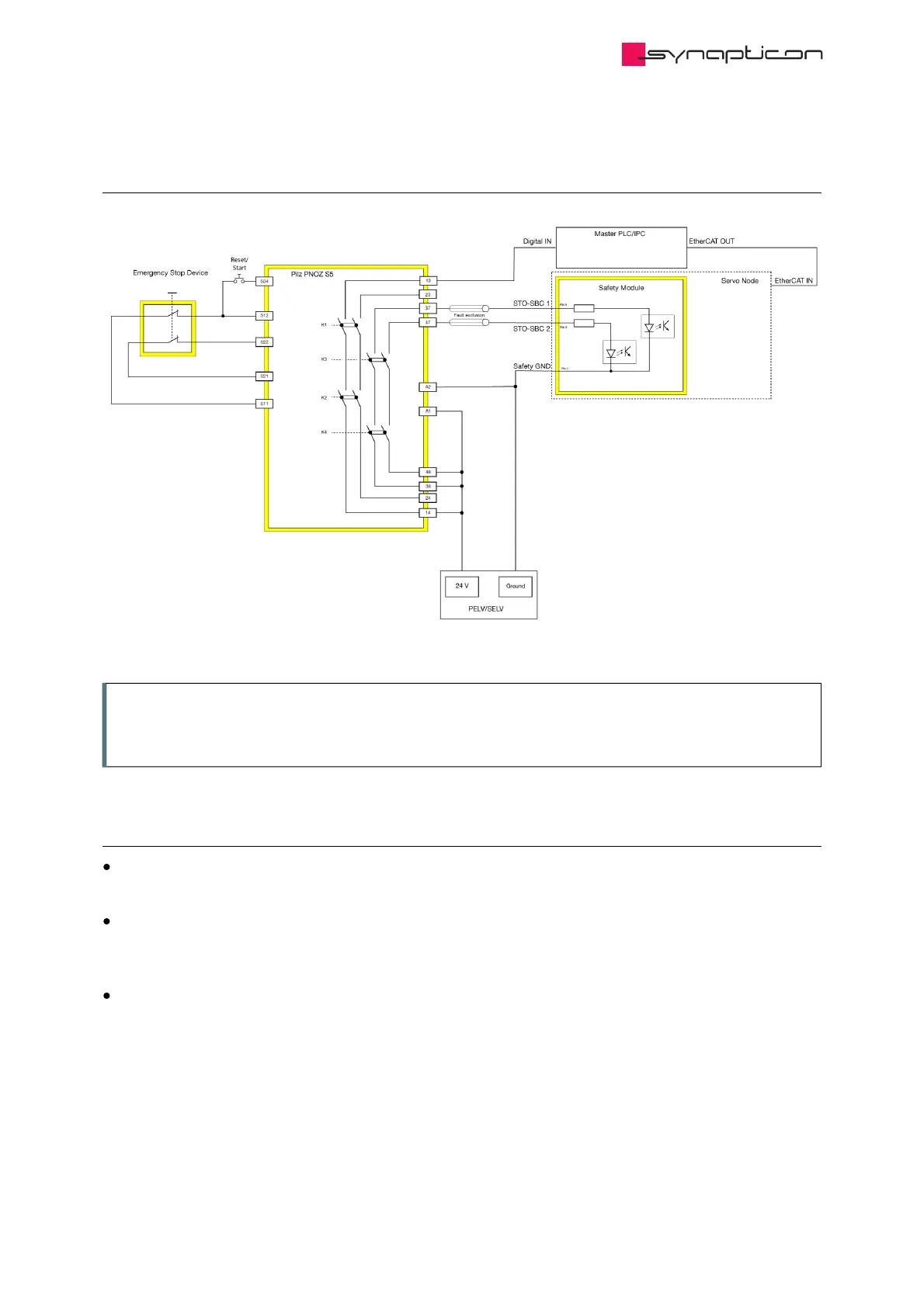
For a PLe, SIL 3 system please regard the requirements for
For a PLe, SIL 3 system please regard the requirements for
fault exclusion between the STO-SBC 1 and
fault exclusion between the STO-SBC 1 and
STO-SBC 2 signals.
STO-SBC 2 signals.
1.5.9.2.3 Configuration
Master PLC/IPC
Program the digital input to request quick stop via EtherCAT Controlword 0x6040
Delay time (in Safety relay)
Configure the time according to your application. The delay time should be longer than the maximum
deceleration time of the application. .
Ramp time (in SOMANET)
Configure the Quick stop deceleration (0x6085) according to your application.