Attention
Attention
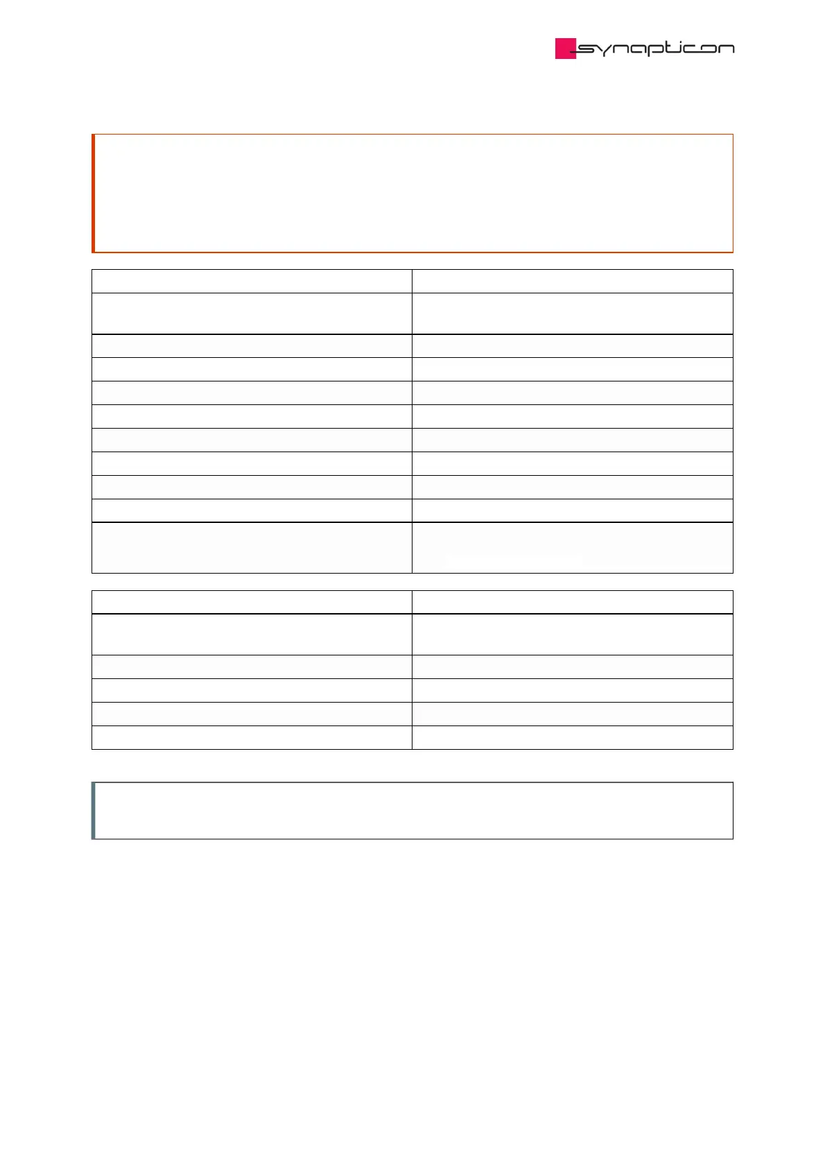
Servo drives including the Safety module shall be used only in Pollution Degree environments class
Servo drives including the Safety module shall be used only in Pollution Degree environments class
PD1 or PD2 according to IEC 61800-5-1: During normal operation only non-conductive pollution
PD1 or PD2 according to IEC 61800-5-1: During normal operation only non-conductive pollution
may occur, temporarily occurring conductivity caused by condensation may only be expected
may occur, temporarily occurring conductivity caused by condensation may only be expected
when the servo drive is out of operation.
when the servo drive is out of operation.
Safe digital inputs (STO-SBC input)
Number of digital inputs 2 (dual-channel safety input for activating STO-
SBC function)
Digital input type according to IEC61131-2:2007 Type 1
Voltage range 0-60 VDC
Max. transient input voltage 80 VDC
Input voltage, logic 1 15-60 V
Input voltage, logic 0 0-5 V
Input current Max. 6 mA (@24 VDC)
Test pulse toleration (OSSD pulses) Max. 1 ms
Reverse voltage protected Yes
Allowed discrepancy between digital inputs 100 ms
See safety diagnostic section
Safe brake output (SBC)
Number of digital outputs 2 (dual-channel safety output for one brake
system)
Max. output voltage Servo drive main power supply (48 VDC)
Min. output voltage 0 V
Max. current. 1 A
Max. peak current. 4 A
Note
Note
This PWM controlled brake is configured by
This PWM controlled brake is configured by
the same object
the same object
as the regular brake.
as the regular brake.