TAC AB, 1998-10-23 0-004-7614-0 (GB), 5:5 (8)
TAC 2413 Handbook Installation
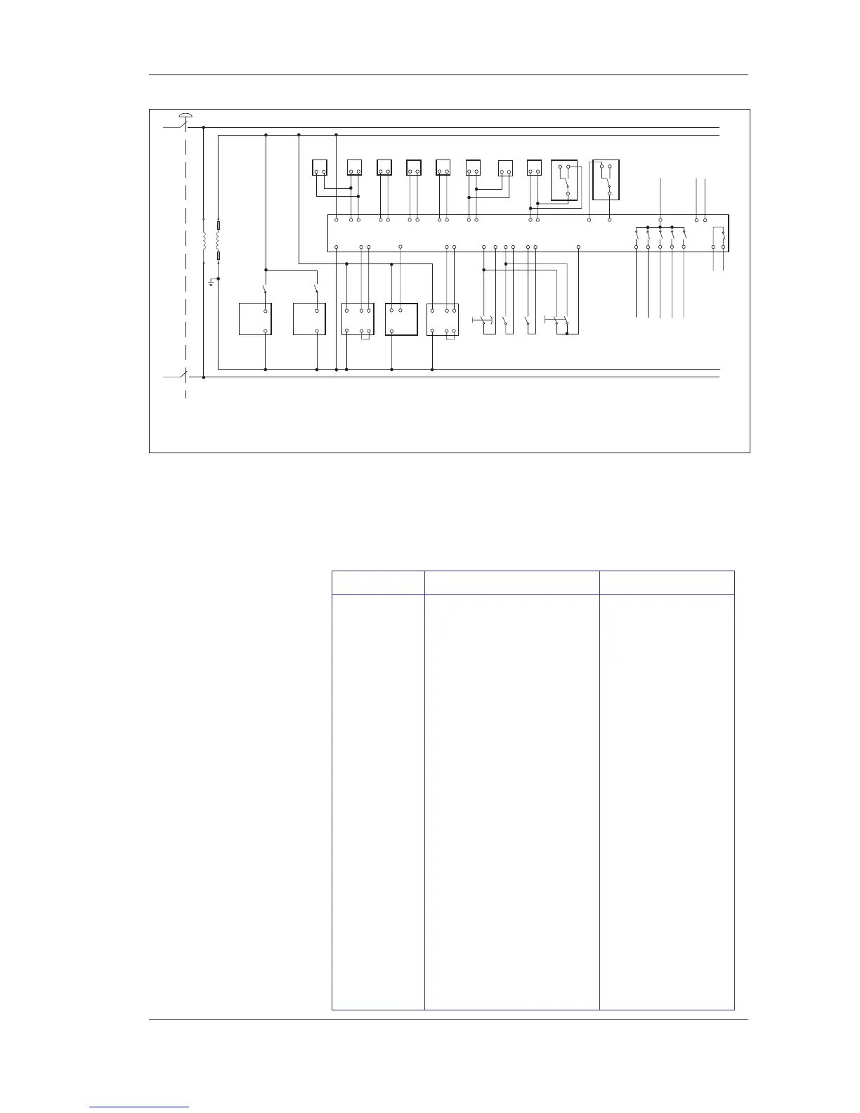
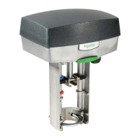
Wiring diagram with the valve actuators EM5, EM42
* Does not need to be connected
** K1: contactor TF01
K2: contactor FF01
N.B.! These drawings only show the units that may be connected
to TAC 2413 using a heat exchanger
as well as waterborne heating and cooling. TAC 2413 may use
other combined functions.
2
1
2
1
G
X1
M
G0
G
X1 M
G0
ST22
N
ST21 SV21 ST41 SV51
K1
24V
T1
230V~
**
K2
G
G0
B1 M
Y1 M
B2
RC1
Y2
M B3 M B4 M
Y3 M
1 2
GT31GT21
21
**
GT11 GT81
21 21
1
1
*
*
*
21
MU1 M
X1 M X2 M X3 M
U2
M
MU4
*
2
GT71GT41
1
GP61
NC NO
C
MU3
K4
K3
K2
K1
KC1
K6
K6
K5
TAC 2413
24V/230V
CO2/SPC
X1 G2
X1 G2
1
1
GP71
NC NO
C
*
21
GX41
*
GX21
21
*
**
2
3
1
*
SN01
P01
N
230V
P01 Pump Heat ing
FF01 Return air fan
Full speed
TF01 Supply air fan
P02 Pump Cooling
Sum
alarm
24V
**
Designation Description Type
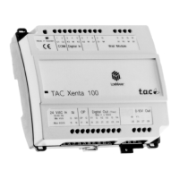
RC1 Controller TAC 2413
ST41 Damper actuator EM 24
SV21 Valve actuator M300 - M750
SV51 Valve actuator M300 - M750
SV21 Valve actuator EM5, EM42
SV51 Valve actuator EM5, EM42
GT11 Temperature sensor EGRL
GT21 Temperature sensor EGL
GT31 Temperature sensor EGU
GT41 Temperature sensor EGL
GT71 Temperature sensor EGL
GT81 Temperature sensor EGXA1 or EGX2
GP61 Pressure sensor KS 500 C2
GP71 Pressure sensor KS 500 C2
GX41/GX21 Smoke detector Other supplier
SNO1 Timer Other supplier
ST21 Damper actuator FMA24
ST22 Damper actuator FMA24
T1 Transformer YT96