37
3.4.2 Series Connection for Positive and Negative Output Voltage
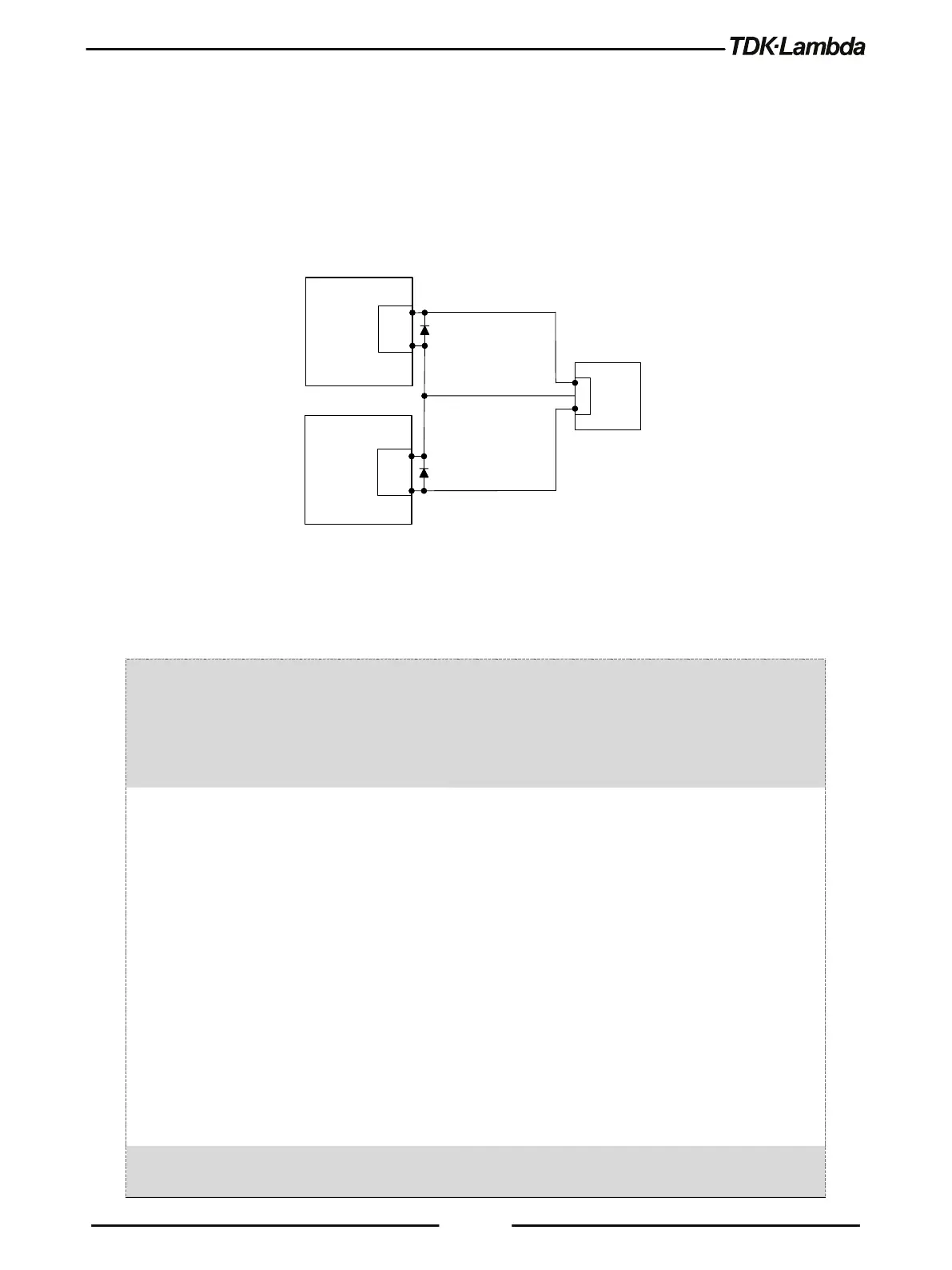
In this mode, two units are configured as positive and negative output.
Set the current limit of each power supply to the maximum that the load can handle without
damage. It is recommended that diodes be connected in parallel with each unit output to prevent
reverse voltage during start-up or in case one of the units shuts down. Each diode should be rated
to at least the power supply rated output voltage and output current. Refer to Figure 3–6 for this
operating mode.
(*)
(*)
POWER
SUPPLY
+
LOAD
COM.
-V
POWER
SUPPLY
-V
+V
-
Figure 3–6: Series Connection for Positive/Negative Output Voltages
(*) Diodes are user supplied.
3.4.3 Remote Programming in Series Operation
Programming by external voltage: The analog programming circuits of this power supply
are isolated from the output potentials. Therefore, the
circuits used to control each series connected unit don't
have to be separated and floated from each other.
Using the SO function and (\PS_OK_OUT)
signal:
DAISY_IN signal (J1-1) serves as Output Shut OFF (SO)
via daisy chain connection.
This signal is used only for the Daisy Chain application,
connected to DAISY_OUT signal (J1-2) of a master unit.
The signal is referenced to the isolated interface
(COM_SELV: J1-11, 12, 13, 14). The function is active
after initial high to low transition.
(\PS_OK_OUT) signal is Power Supply OK– Open
Collector type which indicates output status (DC
On/Off). The signal is referenced to the isolated
interface (COM_SELV: J1-11, 12, 13, 14). The
COM_SELV terminals of the units can be connected to
obtain a single control circuit for the power supplies
Programming by external resistor : Programming by external resistor is possible. Refer to