16
2.4
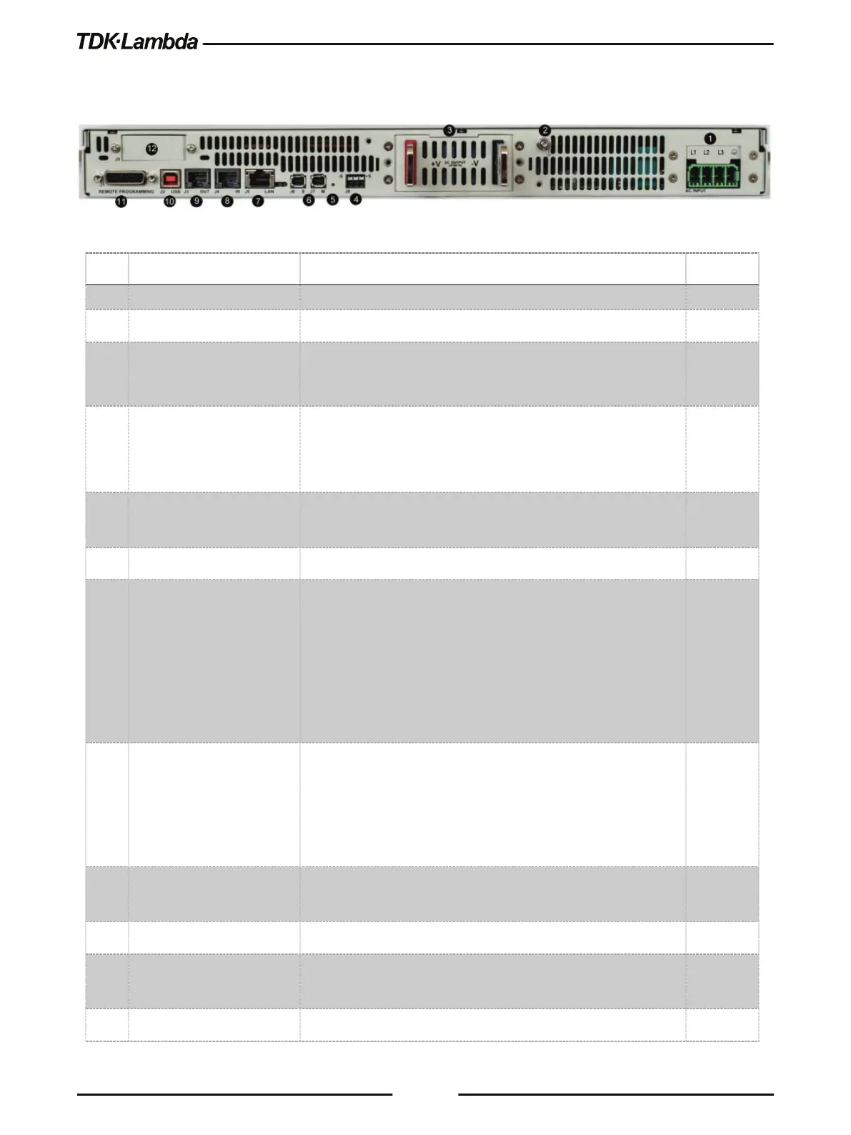
Rear Panel Connections and Controls
Refer to Figure 2–3 and Table 2-3 for description of the Rear Panel connections and controls.
Figure 2–3: Rear Panel Connection and Controls
1 AC Input Connector Connector type: PC 5/ 4-G-7,62.
Functional Ground connection M4x8 Stud.
3 DC Output Bus-Bar /
Connector
Bus-bars for 10V to 100V models,
IPC 5/ 4-GF-7,62 for 150V to 600V models.
4 Remote Sense Connector A Connector for remote sensing connections.
Connect to the load for regulation of the load voltage and
compensation of load wire drop.
5 Reset Button Set default power supply settings (Factory Reset). Press Reset
Button between 5 to 10 sec. Refer to Table 3-5 & Table 3-6.
Master/Slave connectors, mini I/O type
7 LAN Connector +
Indicators *
LAN interface connector, RJ-45 type + LAN status indicators.
Green LED on RJ45 connector – Link / Activity.
Amber LED on RJ45 connector – Speed. Lit – 100Mbps,
otherwise 10Mbps.
Green status indicator (close to RJ45) – Connection active.
Red status indicator (close to RJ45) – LAN fault / Not connected.
8 Serial In Connector RJ-45 type connector, used for connecting power supplies to
RS232 or RS485 port of a computer for remote control
purposes. When using several power supplies in a power
system, the first unit Serial-In is connected to the computer and
the remaining units are chained, Remote-Out to Remote-In.
9 Serial Out Connector RJ-45 type connector, used for chaining power supplies to/from
a serial communication bus.
USB interface connector, type B.
11 Isolated control and
Isolated analog Control and monitoring signals, isolated from
Position for optional communication interface.
Table 2-3: Rear Panel Connections and Controls