83-517-000 Rev. A
150V to 600V Models
The 150V to 600V models have a four terminal wire clamp output connector. The two left terminals are the
positive outputs and the two right terminals are the negative outputs (maximum 30A per terminal). The connector
requirements are as follows:
1. Wires: AWG18 to AWG10.
2. Tightening torque: 4.4 - 5.3 Lb-inch. (0.5 - 0.6Nm).
Follow the instructions below for connection of the load wires to the power supply:
1. Strip approximately 10mm (4 inches) at the end of each of the load wires.
2. Loosen the connector terminal screws.
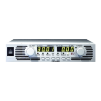
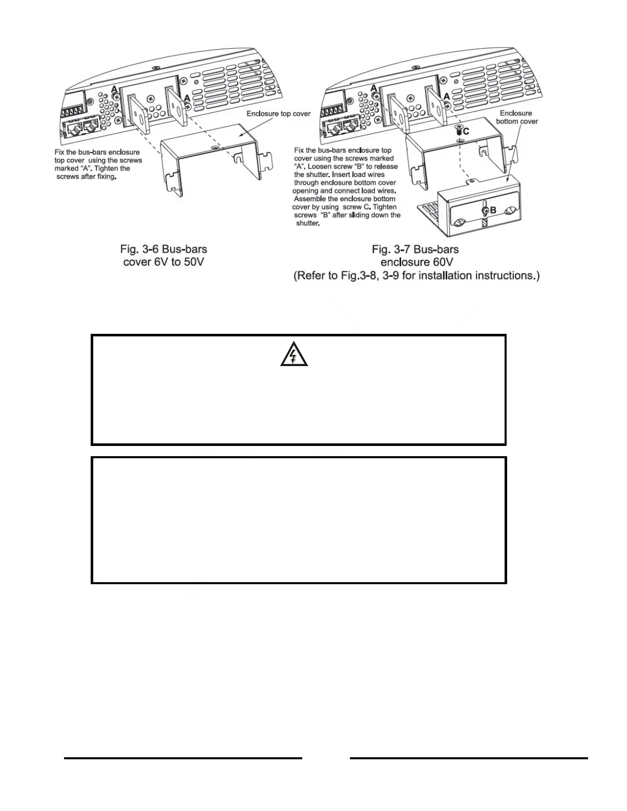
3. Loosen screw marked “B” from the enclosure bottom cover to release the shutter.
4. Insert stripped wires into the enclosure bottom cover opening and then to the terminals. Then tighten the
terminals screws securely (see Figure 3-8).
WARNING
Hazardous voltages may exist at the outputs and the load connections when using a
power supply with a rated Output voltage greater than 40V. To protect personnel
against accidental contact with hazardous voltages, ensure that the load and its
connections have no accessible live parts. Ensure that the load wiring insulation rating
is greater than or equal to the maximum Output voltage of the power supply.
CAUTION
Output Load Wires No Conductors Pretreament: Phoenix contact clamping parts
are designed so that all kinds of copper conductors can be clamped without
pretreatment.
It is forbidden to solder to conductors. The solder tin yields and fractures under high
pressure. The result is increased contact resistance and excessive temperature rise. In
addition corrosion caused by pickling or fluxes has been observed on soldered
conductor ends. Notch fractures at the transition point from the rigid to the flexible
conductor area are also possible.
 Loading...