83-517-000 Rev. A
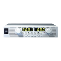
5. Loosen the two chassis screws marked “A” halfway.
6. Assemble the enclosure top cover to the chassis and tighten the screws marked “A” (Tightening torque: 4.8 -
5.3 Lb-inch (0.5 - 0.6Nm)).
Figure 3-8 Load Wires Connection to the Output Connector
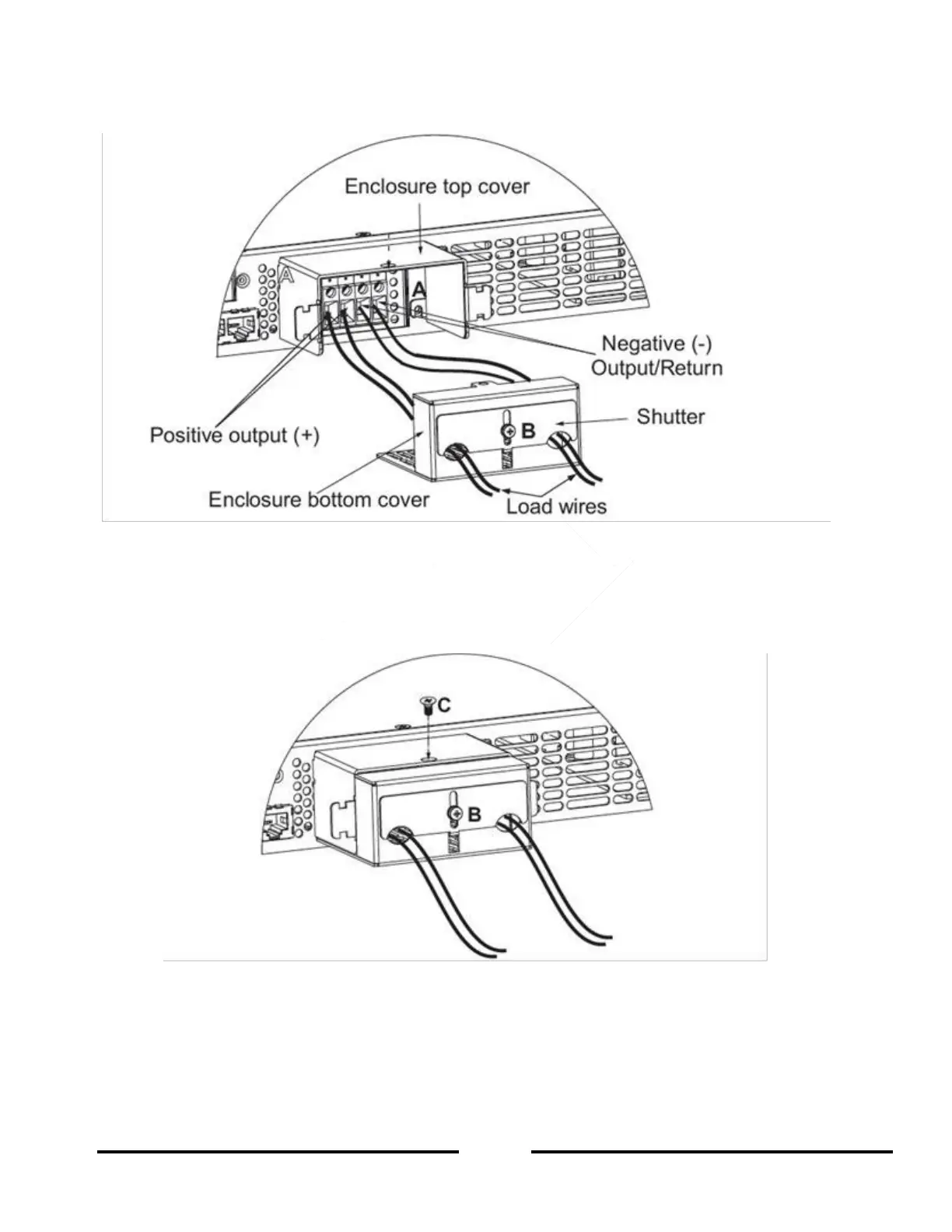
7. Assemble the enclosure bottom cover to it’s place, as shown in Figure 3-9,using the screw marked “C”,
(Tightening torque 4.8-5.3 Lb-inch (0.5 – 0.6Nm)).
8. Slide down the shutter to secure load wires in place, and tighten the screw marked “B”.
Figure 3-9: Shield Assembly
 Loading...