TECDrive20-EU Series Inverter Communication protocol
-133-
ratio value m is 10
n
. Take the table as the example:
0.0–3600.0s (valid when P01.19 is
2)
If there is one figure behind the radix point in the setting range or the default value, then the
fieldbus ratio value is 10. If the data received by the upper monitor is 50, then the "hibernation
restore delay time" is 5.0 (5.0=50÷10).
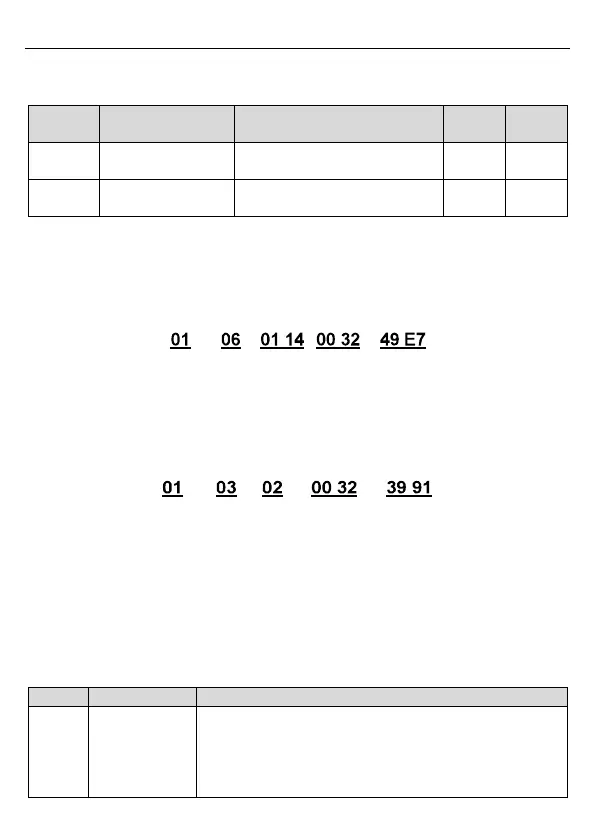
If Modbus communication is used to control the hibernation restore delay time as 5.0s. Firstly,
5.0 can be magnified by 10 times to integer 50 (32H) and then this data can be sent.
Inverter
address
Write
command
Parameter
address
Data number CRC
After the inverter receives the command, it will change 50 into 5 according to the fieldbus ratio
value and then set the hibernation restore delay time as 5s.
Another example, after the upper monitor sends the command of reading the parameter of
hibernation restore delay time, if the response message of the inverter is as following:
Inverter
address
Read
command
Parameter
data
CRC 2-byte
data
Because the parameter data is 0032H (50) and 50 divided by 10 is 5, then the hibernation
restore delay time is 5s.
7.4.4 Error message response
Operation errors may occur in communication-based control. For example, some parameters
can only be read, but a write command is transmitted. In this case, the inverter returns an error
message response. Error message responses are sent from the inverter to the master. The
following table describes the codes and definitions of the error message responses.
The command code received by the upper computer is not
allowed to be executed. The possible causes are as follows:
The function code is applicable only on new devices and is
not implemented on this device.
The slave is in the faulty state when processing this
 Loading...