This function codes defines the V/F curve of
TDI20-EU motor 1 to meet the need of different
loads.
0: Straight V/F curve; applying to the constant
torque load
1: Multi-points V/F curve
2: Torque-down V/F curve (power of 1.3)
3: Torque-down V/F curve (power of 1.7)
4: Torque-down V/F curve (power of 2.0)
Curves 2–4 apply to the torque loads such as
fans and water pumps. Users can adjust
according to the features of the loads to get the
best performance.
5: Customized V/F (V/F separation); in this
mode, V can be separated from f and f can be
adjusted through the frequency reference
channel set by P00.06 or the voltage reference
channel set by P04.27 to change the feature of
the curve.
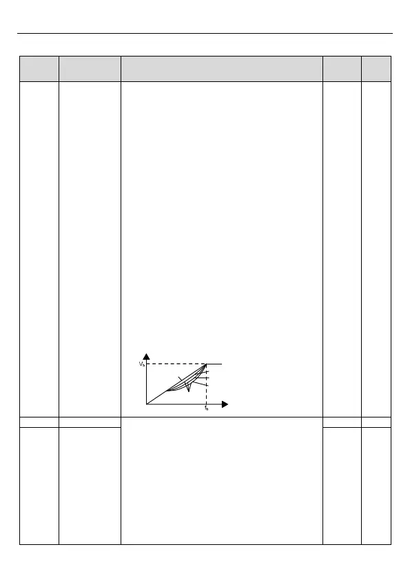
Note: V
b
in the below picture is the motor rated
voltage and f
b
is the motor rated frequency.
Output voltage
Output frequency
Linear type
Square type
Torque step-down V/F curve (power of 1.3)
Torque step-down V/F curve (power of 1.7)
Torque step-down V/F curve (power of 2.0)
Torque boost to the output voltage for the
features of low frequency torque. P04.01 is for
the max. output voltage V
b
.
P04.02 defines the percentage of closing
frequency of manual torque to f
b
.
Torque boost should be selected according to
the load. The bigger the load is, the bigger the
torque is. Too big torque boost is inappropriate
because the motor will run with over magnetic,
and the current of the inverter will increase to