TECDrive20-EU Series Inverter Dimension drawings
-144-
Appendix B Dimension drawings
Dimension drawings of the TDI20-EU are shown as follows. The dimensions are given in mm.
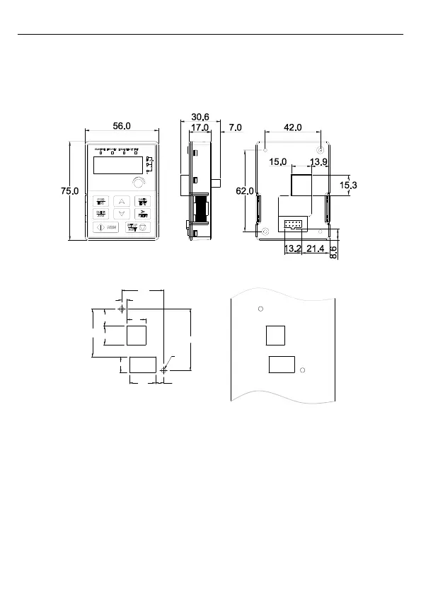
B.1 External keypad structure
Figure B-1 Keypad dimensions
42.0
5.2
62.0
19.0
17.1
48.1
19.0
16.0
26.0
8.0
2-Ø4.5
Figure B-2 Hole-cutting diagram for non-bracket keypad
Note: An external keypad is the optional part for the inverter models of 1PH 230V/3PH 400V
(≤2.2kW) and 3PH 230V (≤0.75kW). For the inverter models of 3PH 400V (≥4kW) and 3PH
230V (≥1.5kW), the keypad can be connected externally.
When connecting the keypad externally, you can install it on the keypad adapter bracket.
There are two types of keypad adapter brackets, which are commonly used with the keypad.
The keypad adapter brackets are optional parts, and their outline and installation dimensions
are shown in Figure B-3.