EasyManua.ls Logo

TEC TECDrive20-EU Series - Cables; Power Cables; Control Cables

TEC TECDrive20-EU Series
171 pages
Print Icon
To Next Page IconTo Next Page
To Previous Page IconTo Previous Page
Loading...
TECDrive20-EU Series Inverter Optional peripheral accessories
-152-
C.3 Cables
C.3.1 Power cables
The sizes of the input power cables and motor cables must meet the local regulation.
Note: If the conductivity of the shielding layer of the motor cables cannot meet the
requirements, separate PE conductors must be used.
C.3.2 Control cables
All analog control cables and cables used for frequency input must be shielded cables.
Relay cables need to be those with metal braided shield layers.
Note:
Analog signals and digital signals cannot use the same cables, and their cables must be
arranged separately.
Check the insulation conditions of the input power cable of an inverter according to the local
regulations before connecting it.
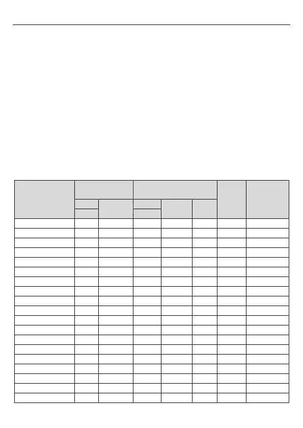
Model
Recommended
cable size (mm
2
)
Size of connectable cable
(mm
2
)

Terminal
screw
Tightening
torque (Nm)
RST
PE
RST
P1, (+)
PE
UVW
UVW
TDI20-0R4G-S2-EU
1.5
1.5
14
14
14
M3
0.8
TDI20-0R7G-S2-EU
1.5
1.5
14
14
14
M3
0.8
TDI20-1R5G-S2-EU
2.5
2.5
14
14
14
M3
0.8
TDI20-2R2G-S2-EU
2.5
2.5
14
14
14
M3
0.8
TDI20-0R4G-2-EU
1.5
1.5
1-1.5
1-1.5
1-1.5
M3
0.8
TDI20-0R7G-2-EU
1.5
1.5
1-1.5
1-1.5
1-1.5
M3
0.8
TDI20-1R5G-2-EU
2.5
2.5
1.56
2.56
2.56
M4
1.13
TDI20-2R2G-2-EU
2.5
2.5
1.56
2.56
2.56
M4
1.13
TDI20-004G-2-EU
2.5
2.5
1.56
2.56
2.56
M4
1.13
TDI20-5R5G-2-EU
4
4
410
410
410
M5
2.3
TDI20-7R5G-2-EU
6
6
410
410
410
M5
2.3
TDI20-0R7G-4-EU
1.5
1.5
11.5
11.5
11.5
M3
0.8
TDI20-1R5G-4-EU
1.5
1.5
11.5
11.5
11.5
M3
0.8
TDI20-2R2G-4-EU
1.5
1.5
11.5
11.5
11.5
M3
0.8
TDI20-004G-4-EU
2.5
2.5
2.56
2.56
2.56
M4
1.13
TDI20-5R5G-4-EU
2.5
2.5
2.56
2.56
2.56
M4
1.13
TDI20-7R5G-4-EU
4
4
410
410
410
M5
2.3
TDI20-011G-4-EU
6
6
410
410
410
M5
2.3
TDI20-015G-4-EU
6
6
410
410
410
M5
2.3

Table of Contents