TECDrive20-EU Series Inverter Installation guidelines
-22-
3. Voltage or current input can be set by dip
switch.
4. Resolution: The minimum AI2/AI3 is
10mV/20mV when 10V corresponds to
50Hz.
1. Output range: 0–10V voltage or 0–20mA
current;
2. Voltage or current output is set by
jumpers or toggle switch;
3. Error ±1%, 25°C;
4. There is only one AO1 for inverters ≤
2.2kW.
1. Contact capacity: 3A/AC250V,
1A/DC30V;
2. Please note that it should not be used as
high frequency switch output;
3. There is only one relay output for
inverters ≤2.2kW.
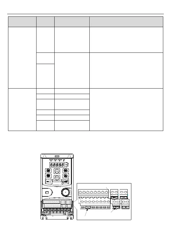
3.2.6 Input/output signal connection figure
Use U-shaped jumper to set NPN mode or PNP mode and the internal or external power
supply. The default setting is the PNP internal mode.
U-shaped jumper between +24V and H2
U-shaped jumper between COM and PW
U-shaped jumper between +24V and H1
Figure 3-13 U-shaped jumper