TECDrive20-EU Series Inverter Product overview
-13-
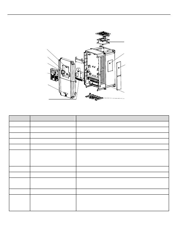
The following figure shows the structure of the inverter (3PH 400V, ≥4kW) (using the 4kW
inverter model as the example).
Figure 2-4 Product structure (Three phase 400V, ≥4kW)
Connect the external keypad
Protect the internal parts and components
Refer to Chapter 4 "Keypad operation"
See Chapter 6 "Fault tracking" for details.
See section 2.5 "Product nameplate" for details.
Cover for the heat
emission hole
Optional, enhancement of the protective degree. It
is necessary to derate the inverter because the
internal temperature is increasing
See Chapter 3 "Installation guidelines" for details.
See Chapter 3 "Installation guidelines" for details.
The cable entry of the
main circuit
Refer to section 2.6 "Model code".
The same as the bar code on the name plate
Note: The bar code is on the middle shell which is
under the cover.