TECDrive20-EU Series Inverter Function parameters
-88-
100.0% of the frequency setting corresponds to
the max. frequency P00.03.
When selecting simple PLC running, set
P10.02–P10.33 to define the running frequency
and direction of all stages.
Note: The symbol of multi-step determines the
running direction of simple PLC. The negative
value means reverse rotation.
P10.04
P10.02
P10.03
P10.05 P10.07
P10.06
P10.31 P10.33
P10.32
ACC time
2 stages
DEC time
2 stages
P10.30
P10.28
Multi-step speeds are in the range of --f
max
–f
max
and it can be set continuously.
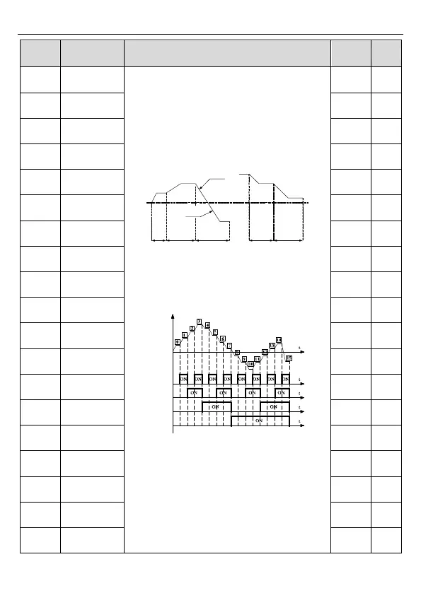
The inverter can set 16 stages speed, selected
by the combination of multi-step terminals 1–4,
corresponding to the speed 0 to speed 15.
Output frequency
Terminal 1
(16)
Terminal 2
(17)
Terminal 3
(18)
Terminal 4
(19)
When terminal1= terminal 2= terminal 3=
terminal 4=OFF, the frequency input manner is
selected via code P00.06 or P00.07. When all
terminals aren't off, it runs at multi-step which
takes precedence of keypad, analog value,
high-speed pulse, PLC, communication
frequency input. Select at most 16 steps speed
via the combination code of terminal 1, terminal
2, terminal 3, and terminal 4.
The start-up and stopping of multi-step running is