SPAZIO FORMA: Service & Maintenance manual - rev. 1.0
Page 3.12
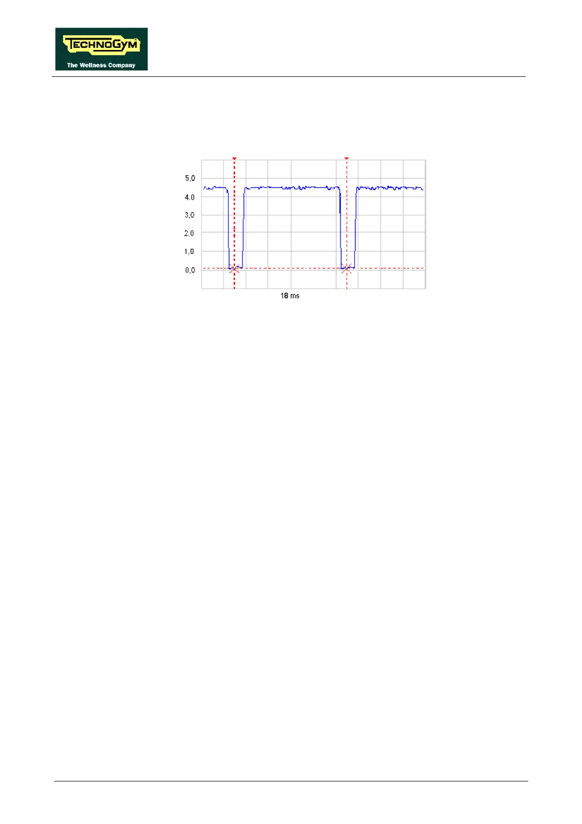
• Trigger signal
This is the signal generated by the CPU board and output (pins 4-5 of connector K16) to the
power isolating board (pins 4-5 of connector J7) to activate the monostable timer. Under normal
operating conditions the signal will appear in the figure below, if viewed with an oscilloscope:
The signal level is 4.4 Vdc with pulses at 0 Vdc at a frequency of 63 Hz. If the emergency is
activated the signal remains constantly at 4.4 Vdc.
• Relay status signal:
This is the signal which the power isolating board (pins 2-5 of connector J7) sends to the CPU
(pins 2-5 of connector K16), with information about the status of the relay. Under normal
operating conditions the level of this signal is 0 Vdc, and it switches to 5 Vdc when the
emergency is activated.
• Inverter power supply voltage
This is the 220 Vac line voltage which supplies the inverter. It comes in from the power inlet
block to pins 8-4 of the relay. The signal output on pins 2-6 of the relay is 0 Vac if the machine
emergency has been activated.
• Up-down motor supply voltage
This is the DC voltage generated by the driver board to supply the up-down motor. It is input on
pins 1-2 of connector J5. Its absolute value is 24 Vdc and, depending on its polarity, the motor
will move either in a clockwise or anticlockwise direction. The signal output on pins 1-2 of
connector J6 is 0 Vac if the machine emergency has been activated.
• Voltage signals for the driver board
These are the voltages generated by the power supply for the driver board, which are input on
connector J2. Pins 5-8 receive a 12 Vdc signal, while pins 6-7 receive a 5 Vdc signal.
The same connector outputs the signals which go to connector J2 on the driver board: 12 Vdc on
pins 1-4, and 5 Vdc on pins 3-2.