SPAZIO FORMA: Service & Maintenance manual - rev. 1.0
Page 6.15
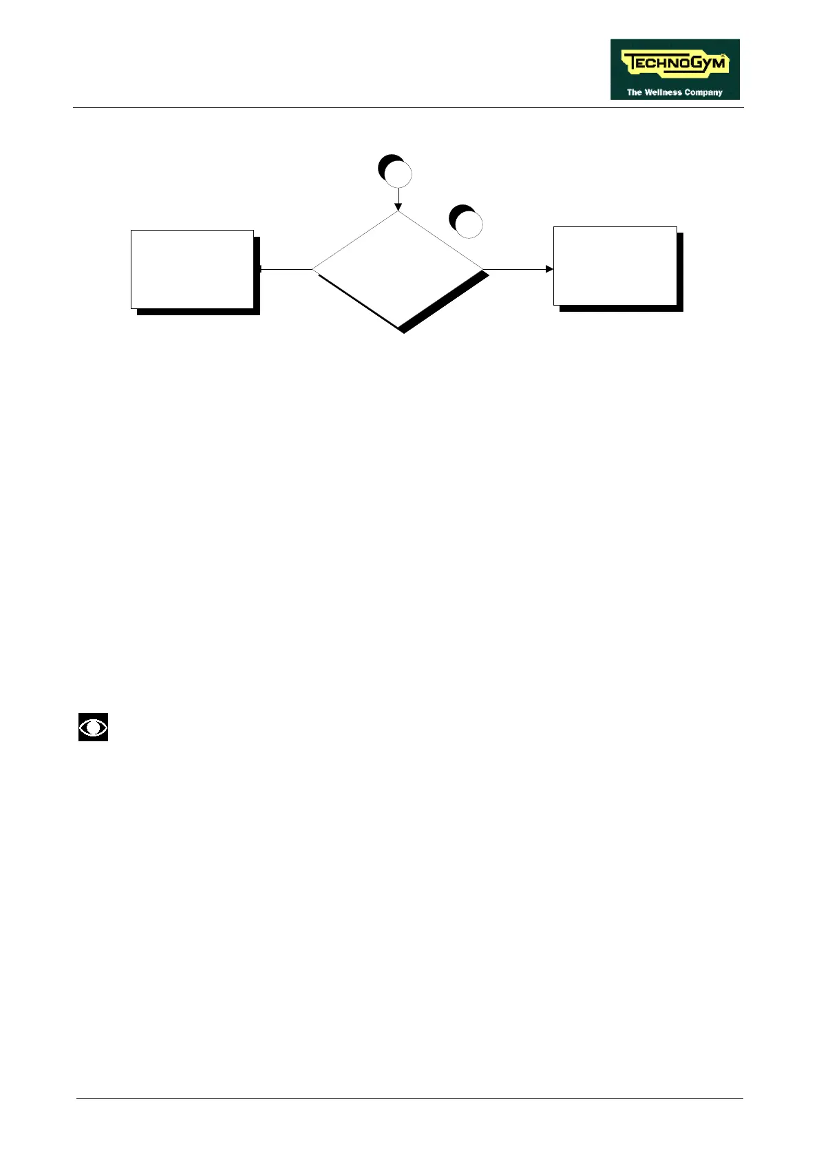
Is the supply v oltage at the
f ilter output correct?
NO
Replace the f ilter
Check and reinstate the
wiring between the f ilter
and inv erter
YES
5
A
Follow the procedure step by step to correctly diagnose the problem. Take particular care with the
checks highlighted by circled numbers, which are described in detail below:
(1) Place the tester probe between terminals L1 and N on the inverter. The measured value should
be 220 VAC.
(2) Place the tester probe between fastons 2 and 6 of the K1 relay on the power isolating board.
The measured value should be 220 VAC.
(3) Place the tester probe between fastons 4 and 8 of the K1 relay on the power isolating board.
The measured value should be 220 VAC.
(4) Disconnect the filter supply cables and place the tester probes across them. The measured
voltage should be 220 VAC.
(5) Disconnect the filter output cables and place the tester probes across the filter terminals. The
measured voltage should be 220 VAC.
This error may be generated even by brief drops in the line voltage due to overloads or
other causes. Therefore, it can be very useful to check the value of the mains voltage
recorded in the inverter memory at the time when the error occurred. To obtain the
mains voltage, the displayed value must be divided by 0.141 .