Appendix A: Specifications
A-2
TDS3000B Serie s User Manual
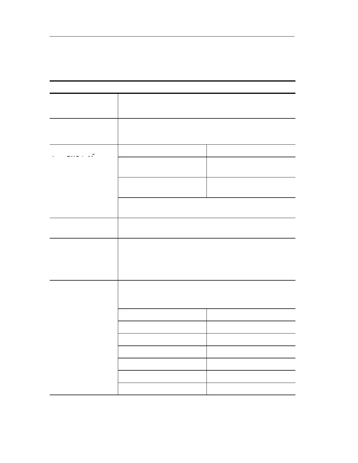
Specifications (cont.)
Inputs
Input coupling DC, AC, or GND
Channel input remains terminated when using GND coupling.
Input impedance,
DC coupled
1MΩ ±1% in parallel with 13 pF ±2 pF, TekProbe compatible
50 Ω ±1%; VSWR ≤ 1.5:1 from DC to 500 MHz, typical
Maximum voltage at
Overvoltage category Maximum voltage
input BNC (1 MΩ)
CAT I Environment (refer to
page A--14)
150 V
RMS
(400 V
pk
)
CAT II Environment (refer to
page A--14)
100 V
RMS
(400 V
pk
)
For steady-state sinusoidal waveforms, derate at 20 dB/decade
above 200 kHz to 13 V
pk
at 3 MHz and above.
Maximum voltage at
input BNC (50 Ω)
5V
RMS
with peaks ≤±30 V
Maximum floating
voltage
0 V from chassis (BNC) ground to earth ground, or
30 V
RMS
(42 V
pk
) only under these conditions: no signal voltages
>30 V
RMS
(>42 V
pk
), all common leads connected to the same
voltage, no grounded peripherals attached
Channel-to-channel
crosstalk, typical
Measured on one channel, with test signal applied to another
channel, and with the same scale and coupling settings on each
channel
Frequency range Crosstalk
≤ 100 MHz ≥ 100:1
≤ 200 MHz ≥ 50:1
≤ 300 MHz ≥ 50:1
≤ 400 MHz ≥ 30:1
≤ 500 MHz ≥ 30:1
≤ 600 MHz ≥ 30:1
 Loading...