Appendix A: Specifications
Trigger
Any channel, HF REJ coupled
1.5 times the D
C-coupled limit
from DC to 30 kHz, attenuates
signals above 30 kHz
Any channel, LF REJ coupled
1.5 times the DC-coupled limits
for frequenc
ies above 80 kHz,
attenuates signals below 80 kHz
Source Sensitivity
Any channel
±8 divisions from center of screen,
±8 divisions from 0 V if LF REJ
trigger co
upled
External trigger ±800 mV
External/10 trigger
±8 V
Trigger lev
el
range
Line
Fixed at the midlevel of the AC line
SET Level TO
50%, typ
ical
Operates with input signals ≥45 Hz
Source
, DC coupled
Sensit
ivity
Any channel ±0.2 divisions
External trigger ±20 m V
External/10 trigger
±200 m
V
Trigger level
accura
cy,
typical
Line
N/A
Trigger holdoff
range
250.
8nsto10s
Logic and
Pulse Trigger
Sen
sitivity,
typical
1.0 division at BNC, D C Coupled, ≥10 mV/div to ≤ 1 V/div (pattern, state,
del
ay, width, and runt triggering)
Slew Rate
Trigger
Se
nsitivity,
typical
Same as the Edge Trigger Sensitivity s pecifications shown earlier in this
appendix.
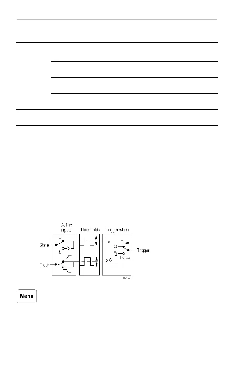
State
P
attern
P
attern with pulse width
2
ns
2
ns
5ns
L
ogic
Triggering
Minimum Logic
T
ime, typical
State minimum logic time: the time that a logic state must be valid before
and after the clock edge to be recognized. Pattern minimum logic time:
the time that a logic pattern must be valid to be recognized. Pattern with
pulse width qualification, minimum logic time: the time that a logic pattern
must be valid to be recognized.
126 TDS3000C Series Oscilloscope User Manual
 Loading...