TSA-200 / TSA-200XT / TSA-240 / TSA-240XT
© 2010 – 2014 Telefire Fire & Gas Detectors Ltd Revision 1.06 July 2014
Page 30 of 79
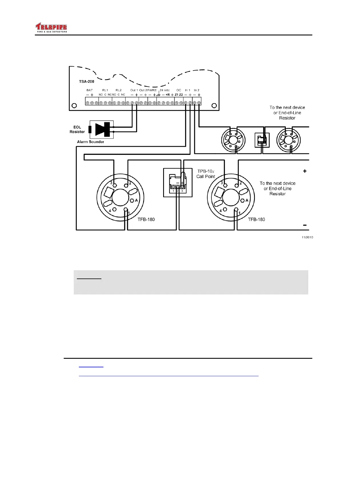
9.7.1 Typical Fire Alarm, Non Extinguishing Connections
Figure 7 Typical Fire Alarm, (Non Extinguishing) Connections
The figure above shows a typical, Fire Detection and Alarm, TSA-200 application.
i
Note
THIS IS A NON EXTINGUISHING EXAMPLE!
The EM1 module is not shown.
It shows the TSA-200 Main Board connected to two zones, where in each zone
detectors and Manual Call Points (MCP) are shown. Also shown is a Fire Alarm Device
(alarm sounder, typically a horn), battery input lines and other lines are omitted for
clarity.
9.8 Connecting the Mains Power and Batteries
SEE SAFETY, page 9
SEE Routing cables into the ECD and maintaining the protection level, page 9.
9.8.1 Connecting AC power and ground wires
Connect the control panel’s AC input cable directly to a dedicated circuit breaker that is
not shared by other appliances or equipment. It is recommended that the circuit breaker
shall be labeled “FIRE ALARM”.
Use a three wire cable (Line, Neutral and Ground wires) of the appropriate gauge and
colors