TSA-200 / TSA-200XT / TSA-240 / TSA-240XT
© 2010 – 2014 Telefire Fire & Gas Detectors Ltd Revision 1.06 July 2014
Page 21 of 79
8 TSA-200 Product Family Control Panel Assembly
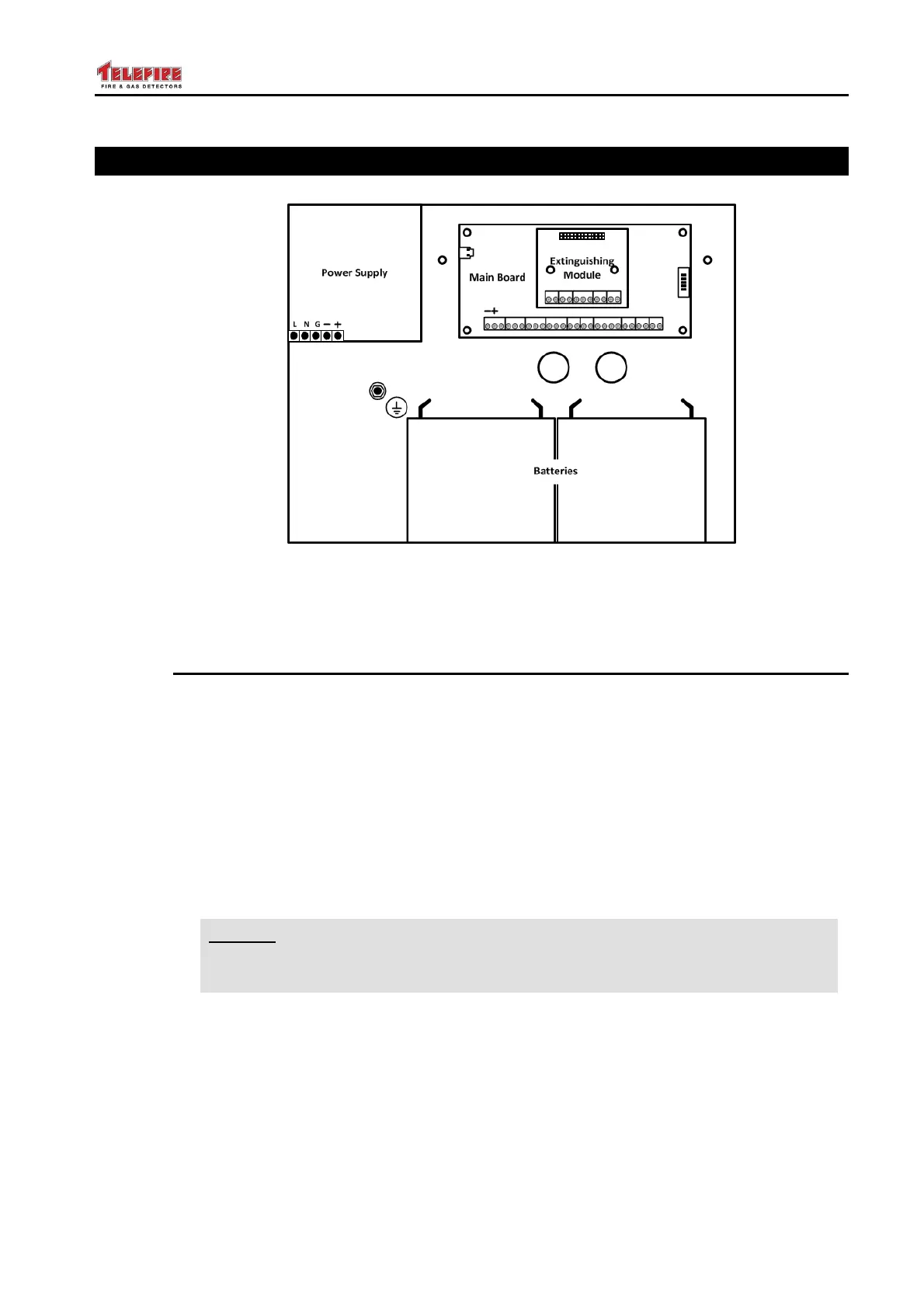
Figure 2 Module location
8.1 The Enclosure and Major Subassemblies
See Fig. 2 "Modules location" and Fig. 4, "Routing TSA-200 cables in its enclosure", for
the location of major subassemblies.
THE TSA-200 product family is housed within a metal enclosure 9a box), which has a
door, hinged to the right, and secured in the closed position by screws.
The door also functions as the front panel, which is comprised of a display/ keyboard
unit serving as the User Interface.
The TSA-200 product family has an internal COTS Power Supply/Charger, located at
the top left corner of the box, the TSA-200M main board, which has two inputs and 3
outputs, the TSA-200EM extinguishing expansion module, which has three inputs and
two outputs.
i
Note
For proper operation of the extinguishing equipment, proprietary and
dedicated adapters are required, as explained before.
Wiring openings knockouts allow for a bottom or top mains cable entry to the Control
Panel box, and a bottom, top, or back, low-voltage cables entry.
Two 12V, 5Ah sealed Lead Acid batteries (connected in series) are positioned at the
bottom of the box.