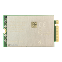
FN990
Family Hardware Design Guide
1VV0301752 Rev. 3 Page 29 of 92 2022-10-07
Not Sub
ect to NDA
4.3.1. Electrical Design Guidelines
The electrical design of the power supply is highly dependent on the power source from
which the power is drained.
4.3.1.1. +5V Source Power Supply Design Guidelines
The desired power supply voltage output is 3.3V. Being the difference between the
input source and the desired output moderate, a linear regulator can be used. A
switching power supply is preferred to reduce power dissipation.
When using a linear regulator, a proper heat sink must be provided to dissipate
the power generated.
A low ESR bypass capacitor of adequate capacity must be provided to cut the
current absorption peaks close to the FN990 Family module. A 100 μF tantalum
capacitor is usually suitable on VPH_PWR.
Make sure that the low ESR capacitor on the power supply output (usually a
tantalum one) is rated at least 10V.
A protection diode must be inserted close to the modem power input to protect the
FN990 Family module from power polarity inversion.
4.3.2. Thermal Design Guidelines
The aim of this paragraph is to provide thermal design guidelines useful for developing a
product with a Telit FN990 modem.
Proper thermal protection design protects against human or component damage under
worst-case conditions.
Furthermore, it reduces the probability of failure and does not adversely affect the use of
the module, and greatly extents the operation time with maximum performance.
For more details, please refer to the thermal design guidelines.
Note: FN990 Family supports different RATs: 3G, 4G and 5G Sub-6.
Based on the Radio Access Technology, the FN990 modem might
exhibithigh current consumption, thus proper thermal designs are
essential to dissipate heat well.

 Loading...