FN990
Family Hardware Design Guide
1VV0301752 Rev. 3 Page 57 of 92 2022-10-07
Not Sub
ect to NDA
7. RF SECTION
Antenna Interface
The antenna connection is one of the most important aspect in the whole application
design as it strongly affects the overall radio performance. Hence, please read and follow
the requirements and the guidelines as carefully as possible.
FN990 Family modules provide four MHF-4 type RF connectors covering the 5G
FR1/LTE/WCDMA bands including GNSS and one MHF-4 type RF connector dedicated to
GNSS.
Warning: When connecting cellular and GNSS antennas to the
module, pay special attention not to damage RF connectors.
7.1.1. Antenna Configuration
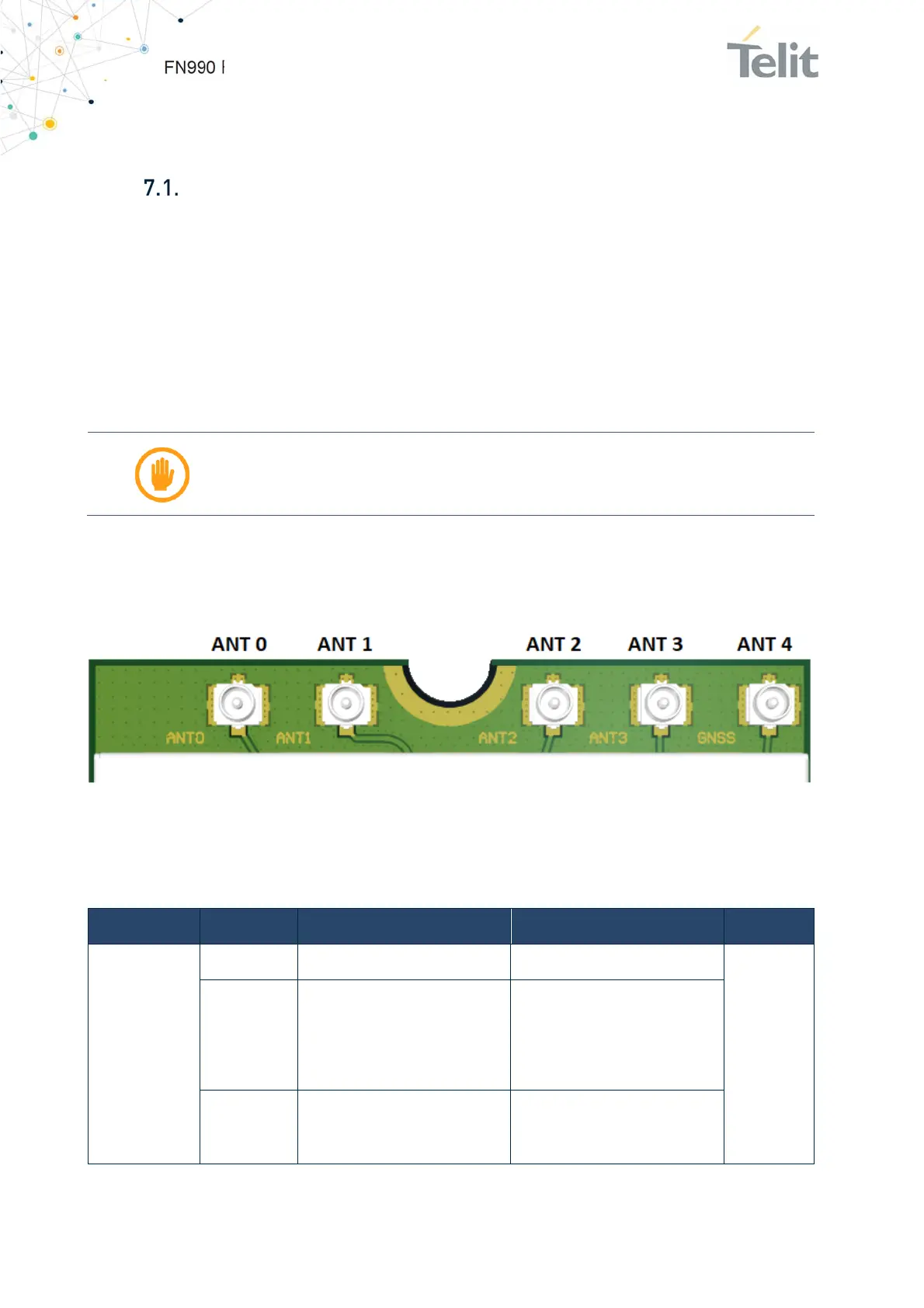
Please refer to the picture below for connector position.
Figure 19: Antenna Configration
Refer to the following antenna configuration assigned.
Antenna port Technology Tx Rx GNSS
ANT 0
WCDMA B1, B2, B4, B5, B6, B8, B19 B1, B2, B4, B5, B6, B8, B19
-
LTE
B1, B2, B3, B4, B5, B7, B8, B12,
B13, B14, B17, B18, B19, B20,
B25, B26, B28, B30, B34, B38,
B39, B40, B41, B66, B71
B1, B2, B3, B4, B5, B7, B8, B12,
B13, B14, B17, B18, B19, B20,
B25, B26, B28, B29(DL), B30,
B32(DL), B34, B38, B39, B40,
B41, B42, B43, B46(DL), B48,
B66, B71
5G NR FR1
n1, n2, n3, n5, n7, n8, n20, n25,
n28, n30, n38, n40, n41, n66,
n71
n1, n2, n3, n5, n7, n8, n20, n25,
n28, n29(DL), n30, n38, n40,
n41, n48, n66, n71, n75(DL),
n77, n78, n79

 Loading...