FN990
Family Hardware Design Guide
1VV0301752 Rev. 3 Page 38 of 92 2022-10-07
Not Sub
ect to NDA
Note: To verify if the FN990 Family has powered up properly, please
follow the indications below:
* Power on trigger time is the interval between VPH_PWR to
FULL_CARD_POWER_OFF_N: this could be null (0 ms) if the
customer application requires turning on the module automatically.
** Monitoring BOOT_OK (Shutdown indicator) pin. When the status
translates to high, the moduleboot-up process is complete. To use
BOOT_OK (Shutdown indicator), the shutdown indication function
must be enabled through the AT#SHDNIND command. (please refer
to the AT Reference Guide document)
*** The stated total boot time is an approximate measure of the
latest SW and HW combination. The boot time may be lengthened or
shortened depending on the module configuration, firmware or
hardware version.
Note: Active low signals are labeled with a name ending with “_N”
Note: To avoid a back-powering effect, it is recommended to prevent
any HIGH logic level signals from being applied to the digital pins of
the module when it is powered OFF or during an ON/OFF transition.
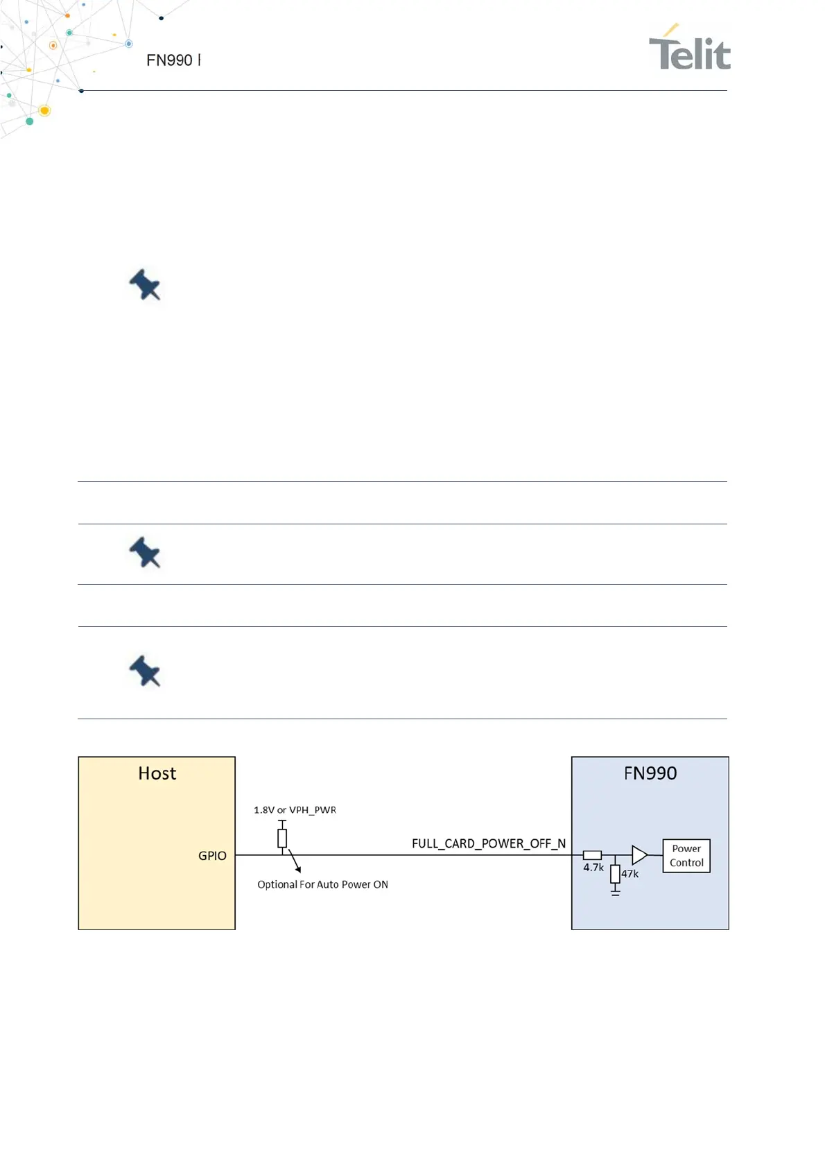
Figure 5: Example Circuit for ON/OFF by FULL_CARD_POWER_N
6.2.2. Power Off
Power off of the device can be done in two different ways:

 Loading...