FN990
Family Hardware Design Guide
1VV0301752 Rev. 3 Page 51 of 92 2022-10-07
Not Sub
ect to NDA
Note: * Unlike the M.2 specicifcation, the UIM_PRESENT pin is set
to active low (Inserted) by default for the Telit unified function.
So FN990 will detect the SIM card insertion when UIM_PRESENT
input is changed from a logic 1 to a logic 0.
If user wants to change UIM_PRESENT pin to active high (inserted),
please refer to AT#SIMINCFG of FN990 AT Commands Reference
Guide.
But if user wants to change the default value of the firmware itself to
reduce unnecessary input of AT commands, please contact Telit
technical support or sales.
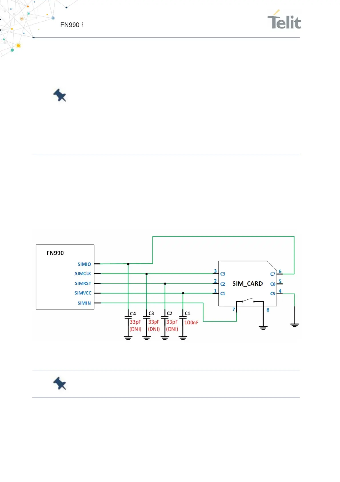
6.3.2.1. SIM Schematic Example
The diagram below shows in particular how the SIM part of the application interface
should be designed.
Figure 14: SIM Schematic Example
Note: FN990 Family modems contain an internal pull-up resistor on
SIMIO. It is not necessary to install external pull-up resistor.
6.3.3. eSIM Interface
FN990 modems include pads for an optional embedded SIM (WLCSP package).

 Loading...