FN990
Family Hardware Design Guide
1VV0301752 Rev. 3 Page 48 of 92 2022-10-07
Not Sub
ect to NDA
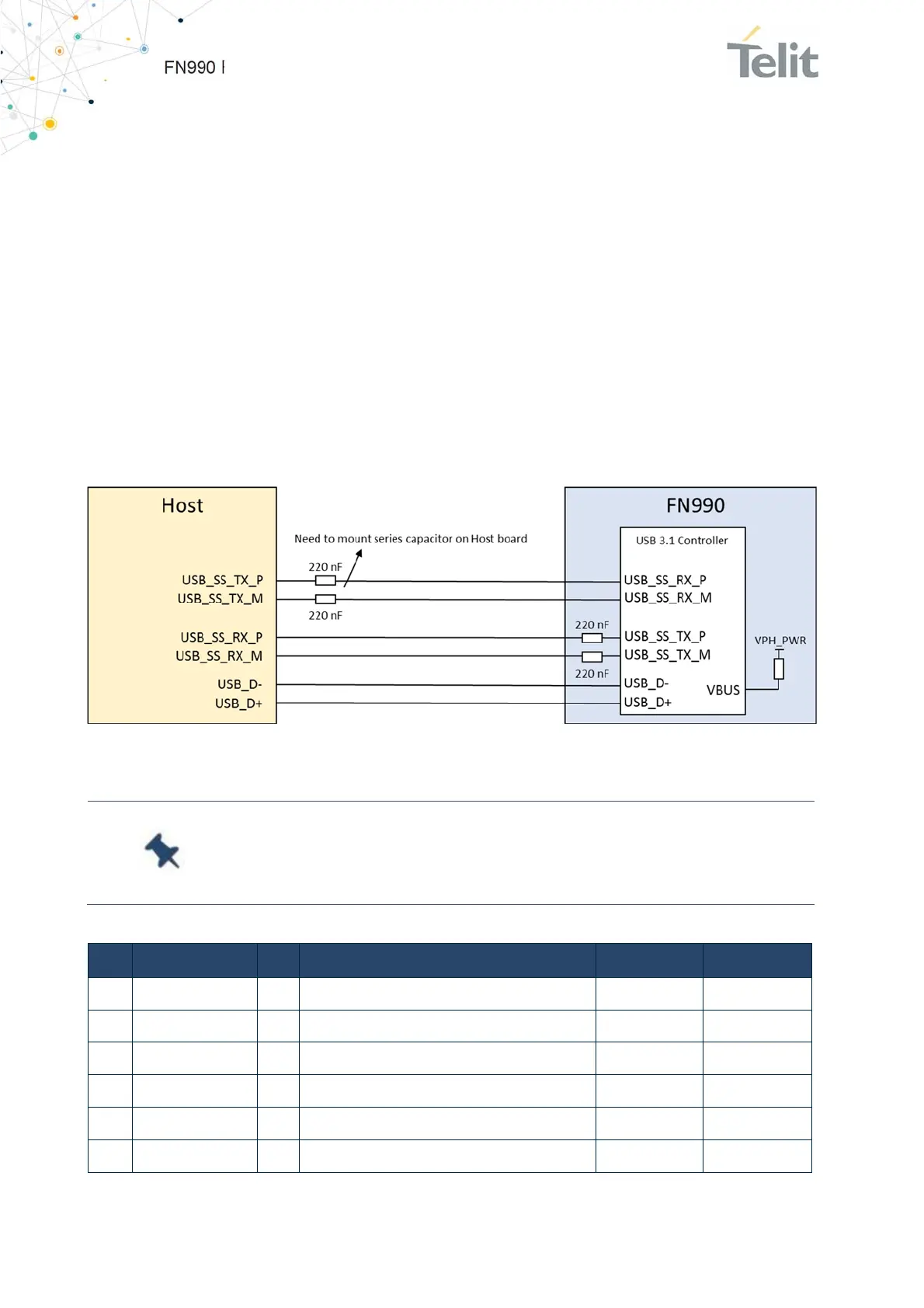
6.3.1.3. USB 3.1 Interface
The FN990 Family modules include super-speed USB 3.1 Gen 2 with high-speed USB 2.0
backward compatibility. It complies with the Universal Serial Bus Specification, revision
3.1 and can be used for control and data transfers as well as for diagnostic monitoring
and firmware update.
The USB port is typically the main interface between the FN990 Family module and
application hardware. USB 3.1 needs AC coupling series capacitors on the TX lines in both
directions.
To interface USB 3.1 with the application board controlling the modem, it is necessary to
install 220 nF capacitor on the USB_SS_RX_P/M lines of the FN990 Family. The series
capacitors are already placed on USB_SS_TX_P/M lines inside FN990 module.
Figure 13: Connection for USB Interface
Note: The USB signal traces must be carefully routed: minimize
trace lengths, number of vias, and capacitive loading. The impedance
value should be as close as possible to 85 Ohm differential.
Pin Signal I/O Function Type Comment
7 USB_HS_DP I/O USB 2.0 Data Plus Analog
9 USB_HS_DM I/O USB 2.0 Data Minus Analog
29 USB_SS_TX_M O USB 3.1 super-speed transmit – Minus Analog
31 USB_SS_TX_P O USB 3.1 super-speed transmit – Plus Analog
35 USB_SS_RX_M I USB 3.1 super-speed receive – Minus Analog
37 USB_SS_RX_P I USB 3.1 super-speed receive – Plus Analog

 Loading...