FN990
Family Hardware Design Guide
1VV0301752 Rev. 3 Page 31 of 92 2022-10-07
Not Sub
ect to NDA
Use a good common ground plane.
Place the power supply on the board to ensure that the high current return paths
in the ground plane do not overlap any noise sensitive circuitry, such as
microphone amplifier/buffer or earphone amplifier.
The power supply input cables must be kept separate from noise sensitive lines,
such as microphone/earphone cables.
RTC
The RTC within the FN990 Family module does not have a dedicated RTC supply pin. The
RTC block is supplied by the VPH_PWR supply.
If the VPH_PWR power is removed, RTC is not maintained so if it is necessary to maintain
an internal RTC, VPH_PWR must be supplied continuously.
Reference Voltage
The 1.8V regulated power supply output is supplied as the reference voltage to a host
board. This output is active when the module is turned ON and turns OFF when the
module is shutdown.
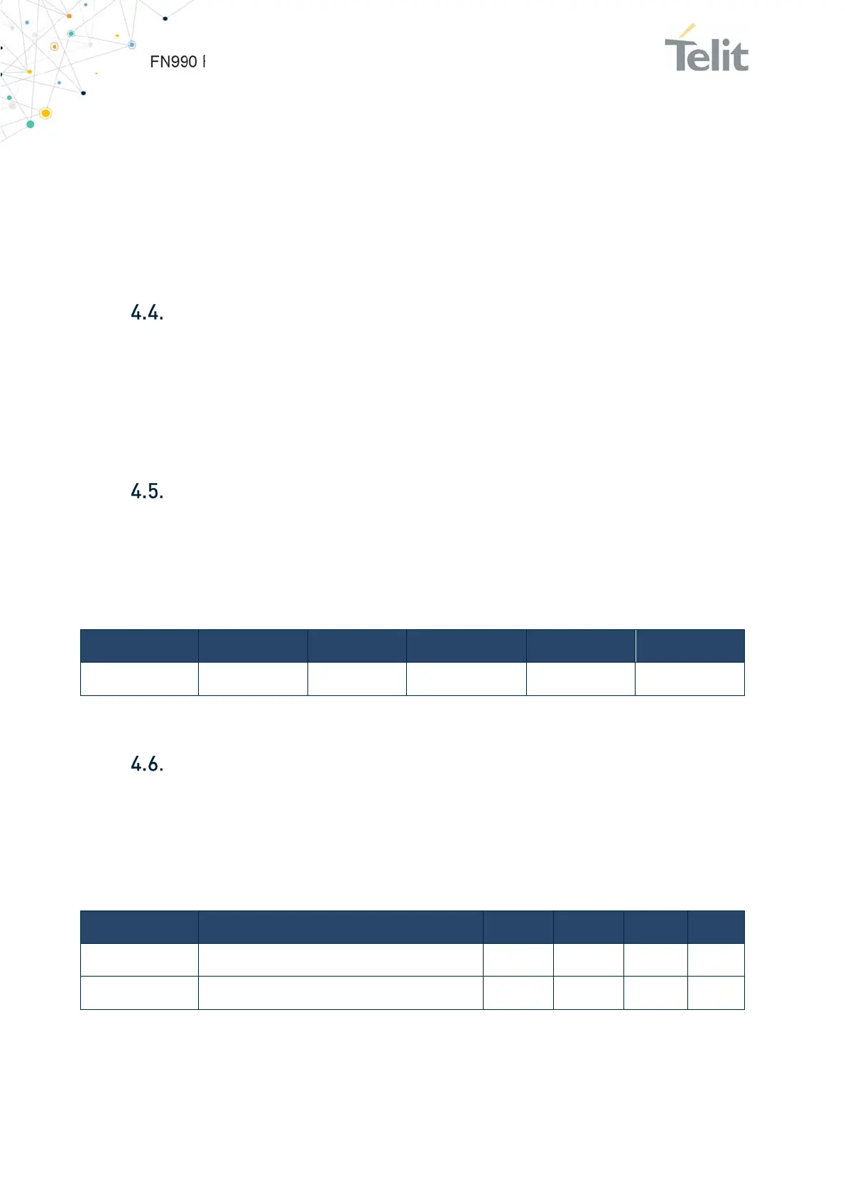
This table lists the reference voltage of the FN990 Family modules.
Pin Signal I/O Function Type Comment
65 VREG_L6B_1P8 O Reference Voltage
Power 1.8V
Table 17: FN990 Family Reference Voltage
Internal LDO for GNSS Bias
The LDO for GNSS bias is applied inside the FN990 Family model.
The voltage supply is generated internally by the FN990 (LDO) and is fed to GNSS active
antenna.
This table below lists the LDO for GNSS bias of FN990 Family modules.
Symbol Parameter Min Typ Max Unit
V
GNSS DC bias
Voltage of internal LDO for GNSS bias 2.9 3.1 3.15 [V]
I
GNSS DC bias
Current of internal LDO for GNSS bias - - 100 [mA]
Table 18: LDO for GNSS bias of FN990 Family

 Loading...