FN990
Family Hardware Design Guide
1VV0301752 Rev. 3 Page 45 of 92 2022-10-07
Not Sub
ect to NDA
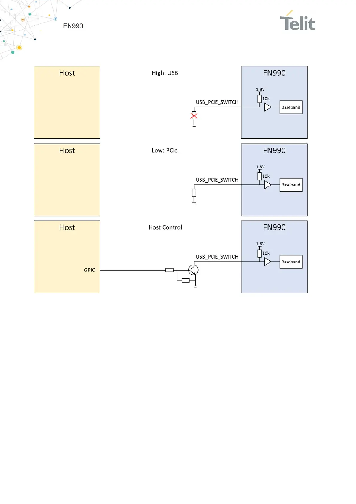
*USB interface is only used as debugging purposes when USB/PCIe Switch pin is low.
Figure 11: Example Circuit for HOST Interface Switch Function
6.3.1.2. PCIe Interface
The FN990 Family module includes PCIe interface. PCIe needs AC coupling series
capacitors on the TX lines in both directions. In order to interface PCIe with the application
board that controls the modem, 0.22 uF capacitors should be installed on PCIE_RX_P/M
lines of the FN990. The series capacitors are already placed on PCIE_TX_P/M lines inside
the FN990.
Internally, VPH_PWR level 100k pull-up resistor is already mounted on PCIE_WAKE_N
and PCIE_CLKREQ_N.
The suggested PCIe interface connection is shown in the diagram below:

 Loading...