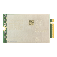
FN990
Family Hardware Design Guide
1VV0301752 Rev. 3 Page 46 of 92 2022-10-07
Not Sub
ect to NDA
Figure 12: Connection for PCIe Interface
Note: The PCIe signals traces must be routed carefully: minimize
trace lengths, number of vias, and capacitive loading. The impedance
value should be as close as possible to 85 Ohm differential.
Pin Signal I/O Function Type Comment
41 PCIE_TX0_M O PCIe transmit 0 – Minus Analog
43 PCIE_TX0_P O PCIe transmit 0 – Plus Analog
47 PCIE_RX0_M I PCIe receive 0 – Minus Analog
49 PCIE_RX0_P I PCIe receive 0 – Plus Analog
53 PCIE_REFCLK_M I PCIe differential reference clock – Minus Analog
55 PCIE_REFCLK_P I PCIe differential reference clock – Plus Analog
50 PCIE_RESET_N I Functional reset to PCIe bus VPH_PWR Default PU
52 PCIE_CLKREQ_N O PCIe reference clock request signl VPH_PWR
Internal 100k
PU
54 PCIE_WAKE_N O PCIe wake-up VPH_PWR
Internal 100k
PU
Table 30: PCIe Interface Signals
Note: Consider placing a low-capacitance ESD protection component
to protect the FN990 against ESD strikes

 Loading...