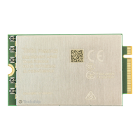
FN990
Family Hardware Design Guide
1VV0301752 Rev. 3 Page 35 of 92 2022-10-07
Not Sub
ect to NDA
Pin Signal I/O Function Type Comment
6 FULL_CARD_POWER_OFF_N I Module On/Off
1.8V /
VPH_PWR
Internal 47k
PD
67 SYS_RESIN_N I Reset Input 1.8V
Internal 100k
PU
65 VREG_L6B_1P8 O Reference Voltage 1.8V Power
* BOOT_OK / Shutdown Indicator O Power ON/OFF Status Check 1.8V
* Can be
assigned to
GPIO
Table 27: Power Interface Signals
6.2.1. Power On
To turn on the FN990 data card, the FULL_CARD_POWER_OFF_N pin must be asserted
high.
Note: To turn on the FN990 module, the SYS_RESIN_N pin must not
be asserted low. If asserted low for more than one second, the
FN990 modem will be reset. Power on can be triggered by
SYS_RESIN_N pin (low level) as well. Even so, please control the
FN990 ON/OFF status by FULL_CARD_POWER_OFF_N pin.
6.2.1.1. Initialization and Activation State
After turning on the FN990 module, the device is not yet fully functional because the
software boot and initialization process takes some time to complete. For this reason, it
is not recommended to start communicating with the FN990 module during the
initialization phase.
The AT command interface is accessible via USB or PCIe port. In general, as shown in
figure below, the FN990 modems become fully operational (in the Activation state) at
least 50 seconds after the FULL_CARD_POWER_OFF_N is asserted.

 Loading...