FN990
Family Hardware Design Guide
1VV0301752 Rev. 3 Page 55 of 92 2022-10-07
Not Sub
ect to NDA
General Purpose I/O
The general-purpose I/O pins can be configured to act in four different ways:
Input
Output
Fast shutdown
Dedicate function (Customer requirement)
Input pins can only report digital values (high or low) present on the pin at the read time.
Output pins can only be set or the pin level can be queried.
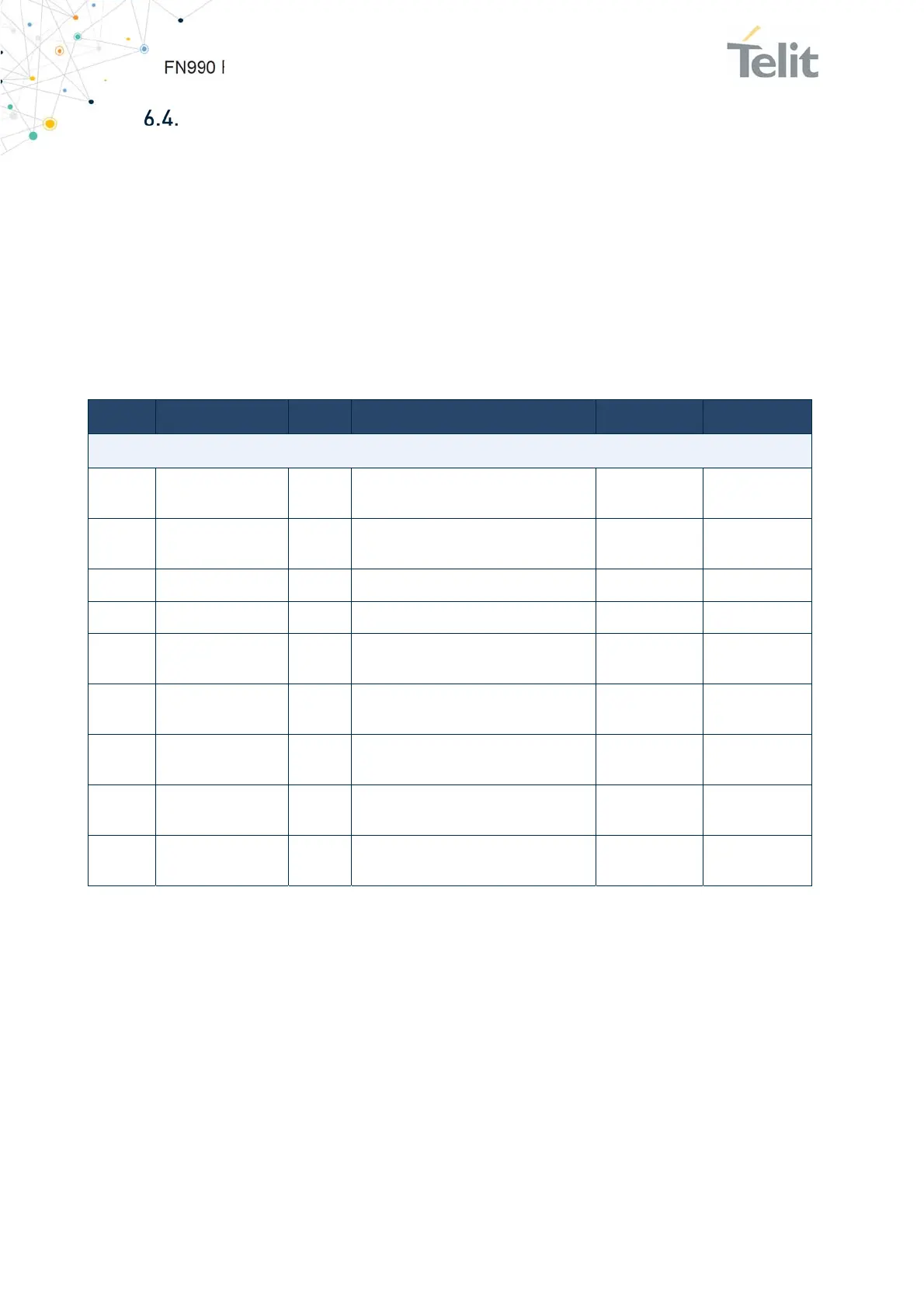
Pin Signal I/O Function Type Comment
General Purpose I/O
68 TGPIO_01 I/O
General Purpose I/O
Can be I2S_CLK
1.8V
25 TGPIO_02 I/O
General Purpose I/O
Can be DPR
1.8V
62 TGPIO_03 I/O General Purpose I/O 1.8V
64 TGPIO_04 I/O General Purpose I/O 1.8V
22 TGPIO_06 I/O
General Purpose I/O
Can be I2S_DIN
1.8V
24 TGPIO_07 I/O
General Purpose I/O
Can be I2S_DOUT
1.8V
28 TGPIO_08 I/O
General Purpose I/O
Can be I2S_WS
1.8V
56 I2C_SDA I/O
I2C Data
Can be TGPIO_09
1.8V
Internal 2.2k
PU
58 I2C_SCL I/O
I2C Clock
Can be TGPIO_10
1.8V
Internal 2.2k
PU
Table 37: General Purpose I/O
6.4.1. Using a GPIO as INPUT
GPIO pins, when used as inputs, can be tied to a digital output of another device and report
its status, provided the device interface levels are compatible with the GPIO 1.8V CMOS
levels.
If a digital output of a device is tied to GPIO input, the pin has interface levels different
than 1.8V CMOS. It can be buffered with an open collector transistor with a 47K ohm pull-
up resistor to 1.8V.

 Loading...