FN990
Family Hardware Design Guide
1VV0301752 Rev. 3 Page 44 of 92 2022-10-07
Not Sub
ect to NDA
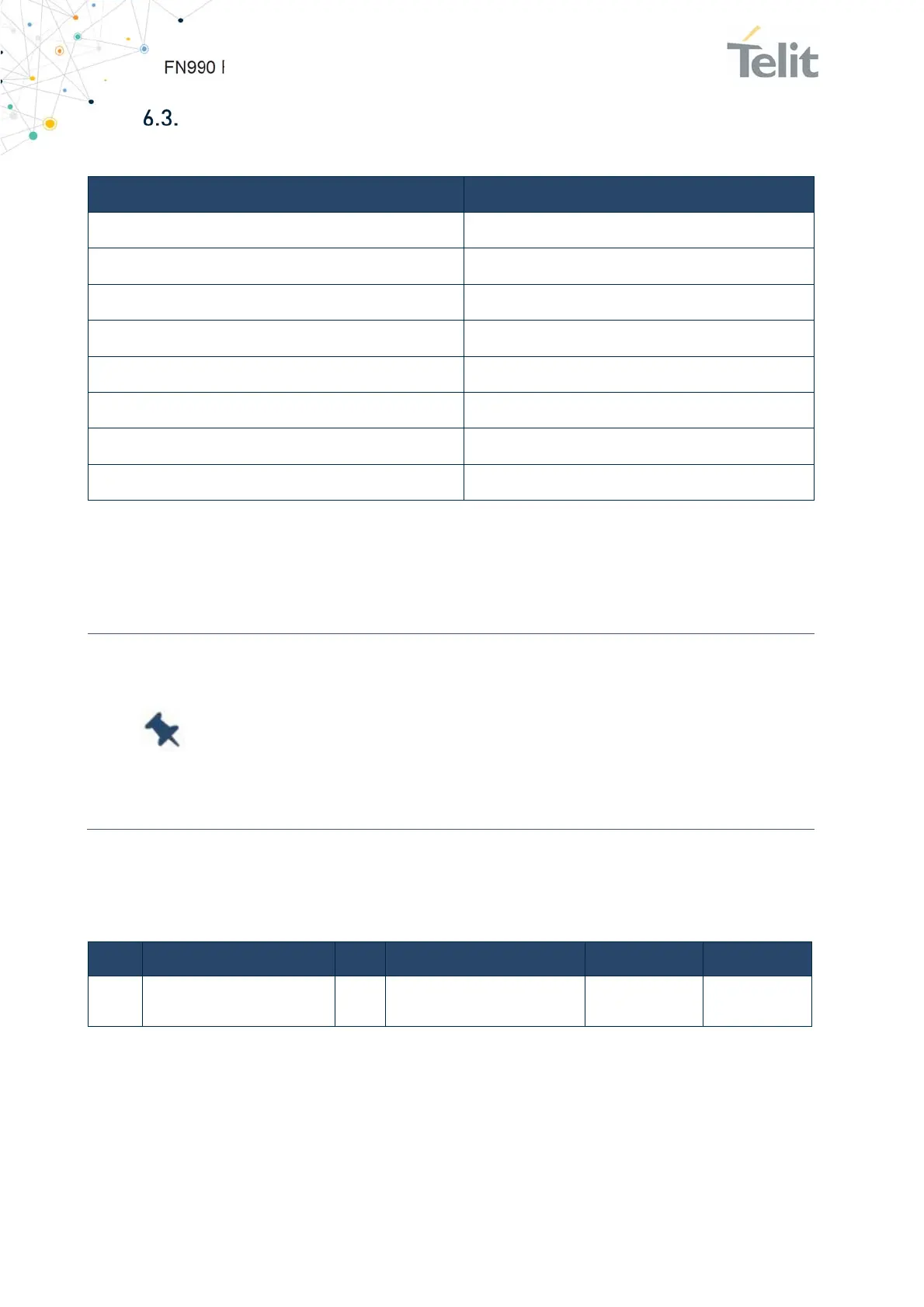
Communication Ports
The below table summarizes all the hardware interface of the FN990 Family module.
Interface Description
PCIe Peripheral Component Interconnect Express Gen 4.0
USB USB 3.1 Gen 2 interface
USIM x2 dual voltage each (1.8V / 2.95V)
eSIM
Embeded SIM (optional)
I2C
Inter-Integrated Circuit
I2S
Inter-IC Sound
Control Interfaces
W_DISABLE_N, WAKE_ON_WAN_N, LED, DPR
Antenna ports
x4 Cellular, 1 for GNSS
Table 28: FN990 Family Hardware Interfaces
6.3.1. Host Interface
Note: FN990 M.2 data card supports USB 3.1 Gen 2 and PCIe Gen 4
respectively. This means USB 3.1 and PCIe 4.0 interface cannot be
used at the same time.
Basically, the host interface operates as USB 3.1 Gen 2: if the
application requires to use PCIe Gen 4.0 host interface switch must
be used.
6.3.1.1. Host Interface Switch Function
This chapter describes the host interface switch functions.
Pin Signal I/O Function Type Comment
20 USB_PCIE_SWITCH I Swich Host Interface 1.8V
Internal 10k
PU
Table 29: Host Interface Switch Pin
FN990 Family M.2 Card determines the host interface by checking the status of
USB_PCIE_SWITCH pin at the beginning of the power on sequences.
High(Default): USB 3.1 or USB 2.0
Low: PCIe 3.0 + (USB 3.1 or USB 2.0)*

 Loading...