FN990
Family Hardware Design Guide
1VV0301752 Rev. 3 Page 43 of 92 2022-10-07
Not Sub
ect to NDA
Note: *Shutdown Indicator is an optional function. If SHDIND is
enabled, it can verify the status via SHDIND function.
Please refer to the AT commands user guide document.
** The stated total reset time is an approximate measure of the latest
SW and HW combination. The shutdown time may be lengthened or
shortened depending on the SW configuration, SW or HW version.
Note: Unconditional hardware reset must be used only as an
emergency procedure, and not as a normal power-off operation.
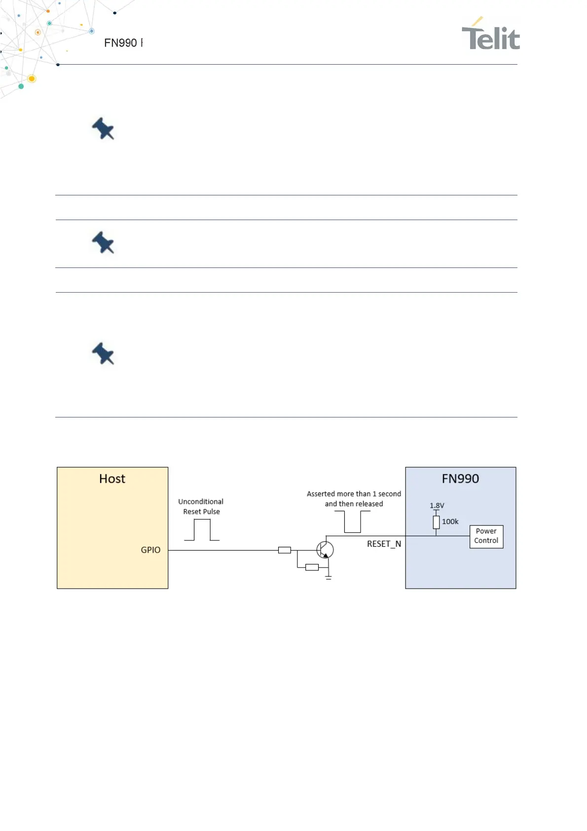
Note: Do not use any pull-up resistor on the RESET_N line or any
totem pole digital output. Using a pull-up resistor may cause latch-
up problems on the FN990 Family power regulator and improper
functioning on the module.
The RESET_N line must be connected only in an open-collector
configuration.
Below figure shows a simple circuit for this action.
Figure 10: Example Circuit for RESET by SYSTEM_RESET_N

 Loading...