49
Tempest900 2-Channel Operating Manual
4-Wire (Matrix) Intercom Interface
4-Wire intercom systems use two pairs of wires to carry one full duplex channel of intercom audio - one pair for send and the second pair for
receive. In addition to intercom audio, most systems have separate data lines that carry system data from the matrix to the remote devices. The
Tempest 4-Wire connection is an audio-only interface to 4-Wire systems. Data can be present on the input cable but no data is utilized in the
Tempest BaseStation.
Steps to Congure a 4-Wire Intercom Connection
• Select 4-Wire connection for the appropriate channels.
• Make the physical connections with RJ-45s to the Tempest BaseStation and the 4-Wire system.
• Congure the 4-Wire system to recognize the Tempest Wireless system.
• Adjust IN/OUT volume levels between the Tempest Wireless System and the 4-Wire system as needed.
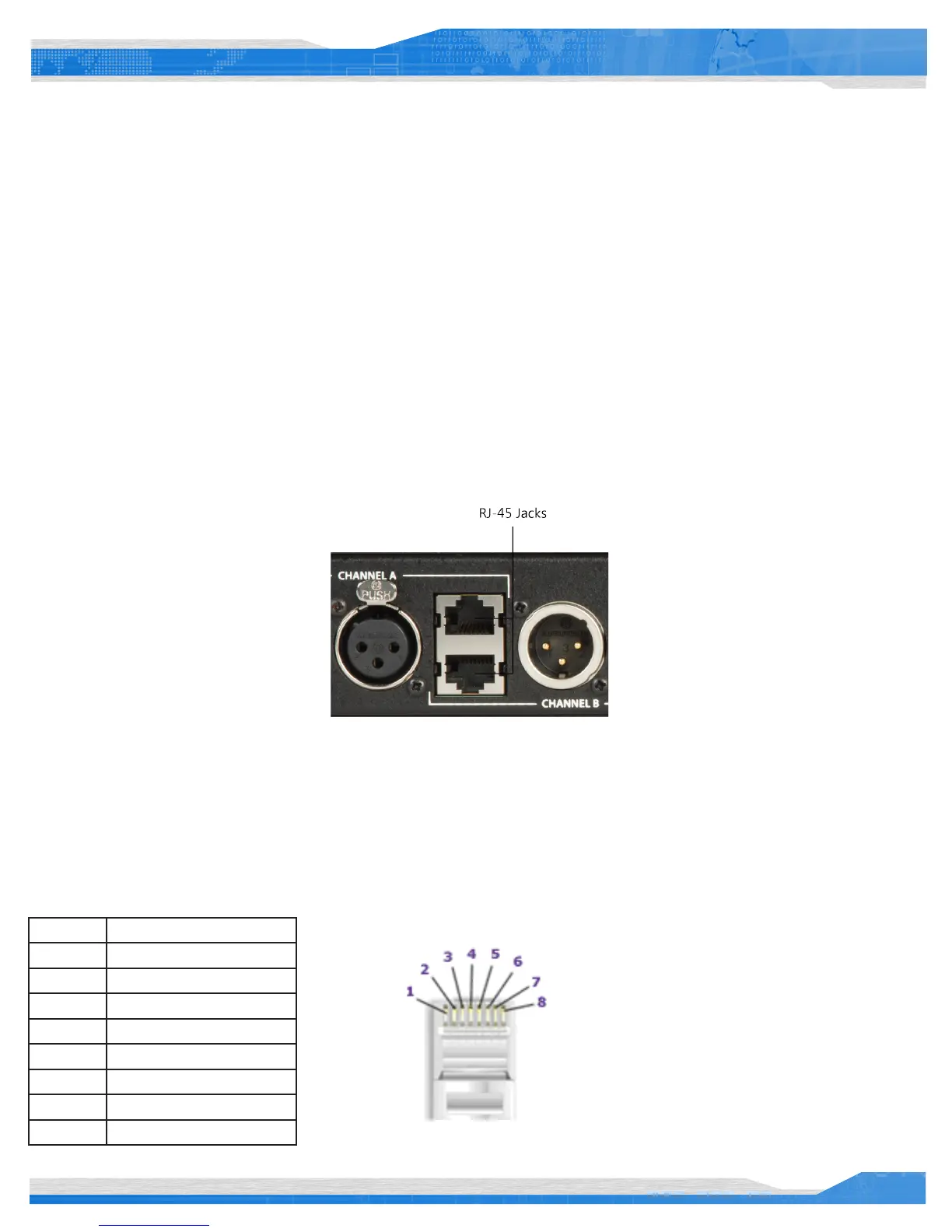
Connect the 4-Wire intercom system to the desired channel RJ-45 jack on the rear panel of the Tempest BaseStation. Select the 4-Wire setting
as described in “Wired Intercom Conguration Controls.” That is all that is necessary for Tempest to be ready to communicate with the 4-Wire
system. Perform any necessary conguration for the 4-Wire intercom System and the communication link should be complete.
The top RJ-45 jack is for Channel A and the bottom RJ-45 jack is for Channel B.
You may choose to adjust the IN/OUT levels on the front of the BaseStation if the volume level between the systems is not acceptable.
Wiring schemes vary and it is important to ensure that the cable is wired correctly for proper system operation. Tempest utilizes RJ-45 jacks for
4-Wire connection to the BaseStation. Only two pairs of wires are utilized - one to send audio and one to receive audio. A standard CAT-5 patch
cable can be used to connect between the matrix and the Tempest system.
Tempest 4-Wire / RJ-45 Connection
Pin # Use
1 No Connection
2 No Connection
3 Audio Output (+)
4 Audio Input (+)
5 Audio Input(-)
6 Audio Output (-)
7 No Connection
8 No Connection