32
5. Test Execution ‘TERRATEST 4000 STREAM’ (‘TERRATEST 6000 BLE’ see page 38)
5.1 Preparing the Testing Point
Place the load plate on the ground, ensuring full and even contact between the
load plate and the ground. Create a smooth and level surface on the area where
the load plate will be placed. This can be done by moving the load plate back
and forth, or by using appropriate tools (such as a trowel). Remove any loose
soil from the area. In case of soil irregularities, spread a thin levelling layer of
fine-grained quartz sand. Make sure to add only a few millimetres; it should
compensate only for uneven patches under the load plate. Next, place the load
plate on top and move it back and forth to reduce the thickness of the sand
layer. Full contact between the load plate and the test area is essential.
5.2 Test Execution / Data Input Function
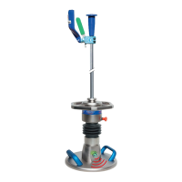
After preparing the testing point and placing the load plate on the ground, place the loading device in the
centre of the sensor dome on the load plate.
Connect the sensor dome of the load plate with the testing computer, using the measuring cable.
Press and hold the start button to turn on the testing computer. To activate the backlight of the graphic
display, press the start button for approximately three seconds, when turning on the device, until the start
screen switches automatically to ‘STATUS REQUEST’.
FR 30/06/17 15:50:22
OK
OK
OK
GPS
6,3V
FR 30/06/17 15:50:22
?
?
?
GPS
6,3V
KALIBRIERT BIS 03/20
V022.3
30
STREAM
TERRATEST4000
When turning on the testing computer with the backlight off, the start
screen will show the ‘TERRATEST 4000 USB’ llogo, the firmware ver-
sion number as well as the expiration date of calibration as initial screen
for approximately three seconds, until the start screen switches automa-
tically to STATUS REQUEST.
STATUS REQUEST checks sensor connection, battery charge, USB stick
respectively readiness to ‘STREAM’ dongle and GPS operation and
acknowledges availability by ‘OK’ in the display, and the voice output by
‘Welcome to TERRATEST. Sensor OK. Start test’ If one of these features is
unavailable, display shows ‘?’ instead. Absent sensor connection is noti-
fied by voice output ‘No sensor’. Checking the GPS connection can take
2-3 minutes. If the sensor connection is not established, the computer
will not progress to the measuring mode and no test can be performed.
The current battery charge is visualized by charge level of battery as well
as by voltage value below the battery symbol.
If the USB stick respectively the ‘STREAM’ dongle is not recognized at
once, turn the device OFF; pull off the USB stick or ‘STREAM’ dongle,
insert the element again and switch ON the device again. If the problem
persists verify whether the concerned element is correctly formatted. In
case of need, formatting procedure can be carried out at the PC by a right
clicking on the drive symbol of USB stick or ‘STREAM’ dongle in context
menu ‘Format…’.
Return to measurement mode by briefly pressing Start button. Long pres-
sing start button opens text input mode, featuring 5 predefined soil lay-
ers and two editable text field for selection.
STATUS REQUEST
START SCREEN
TEXT INPUT MODE
NATUR. GROWN SOIL
SUBGRADE
BASE COURSE
GRAVEL BASE LAYER
FROST PROTECTION
PERMANENT DATA
FREELY EDITABLE
EXIT SET
→
→