CC1101
SWRS061H Page 16 of 98
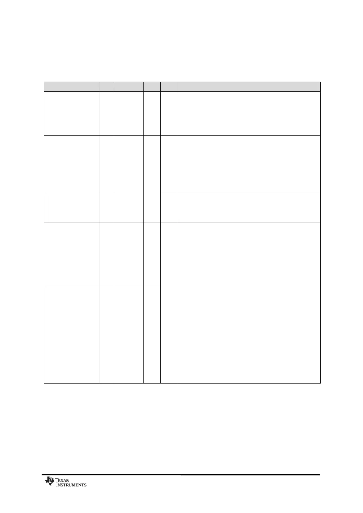
4.3 RF Transmit Section
T
A
= 25C, VDD = 3.0 V, +10 dBm if nothing else stated. All measurement results are obtained using the CC1101EM reference
designs ([1] and [2]).
Differential load
impedance
315 MHz
433 MHz
868/915 MHz
122 + j31
116 + j41
86.5 + j43
Differential impedance as seen from the RF-port (RF_P and
RF_N) towards the antenna. Follow the CC1101EM reference
designs ([1] and [2]) available from the TI website
Output power,
highest setting
315 MHz
433 MHz
868 MHz
915 MHz
Output power is programmable, and full range is available in all
frequency bands. Output power may be restricted by
regulatory limits.
See Design Note DN013 [15] for output power and harmonics
figures when using multi-layer inductors. The output power is
then typically +10 dBm when operating at 868/915 MHz.
Delivered to a 50 single-ended load via CC1101EM
reference designs ([1] and [2]) RF matching network
Output power, lowest
setting
Output power is programmable, and full range is available in all
frequency bands
Delivered to a 50 single-ended load via CC1101EM
reference designs ([1] and [2]) RF matching network
Harmonics, radiated
2
nd
Harm, 433 MHz
3
rd
Harm, 433 MHz
2
nd
Harm, 868 MHz
3
rd
Harm, 868 MHz
2
nd
Harm, 915 MHz
3
rd
Harm, 915 MHz
Measured on CC1101EM reference designs ([1] and [2]) with
CW, maximum output power
The antennas used during the radiated measurements
(SMAFF-433 from R.W. Badland and Nearson S331 868/915)
play a part in attenuating the harmonics
Note: All harmonics are below -41.2 dBm when operating in
the 902 – 928 MHz band
Harmonics, conducted
315 MHz
433 MHz
868 MHz
2
nd
Harm
other harmonics
915 MHz
2
nd
Harm
other harmonics
< -35
< -53
-43
< -45
-36
< -46
-34
< -50
dBm
dBm
dBm
dBm
dBm
dBm
dBm
dBm
Measured with +10 dBm CW at 315 MHz and 433 MHz
Frequencies below 960 MHz
Frequencies above 960 MHz
Frequencies below 1 GHz
Frequencies above 1 GHz
Measured with +12 dBm CW at 868 MHz
Measured with +11 dBm CW at 915 MHz (requirement is -20
dBc under FCC 15.247)