CC1101
SWRS061H Page 66 of 98
often prevents this kind of continuous data streaming and reduces the effective data rate).
28.7 Battery Operated Systems
In low power applications, the SLEEP state
with the crystal oscillator core switched off
should be used when the
CC1101
is not active.
It is possible to leave the crystal oscillator core
running in the SLEEP state if start-up time is
critical. The WOR functionality should be used
in low power applications.
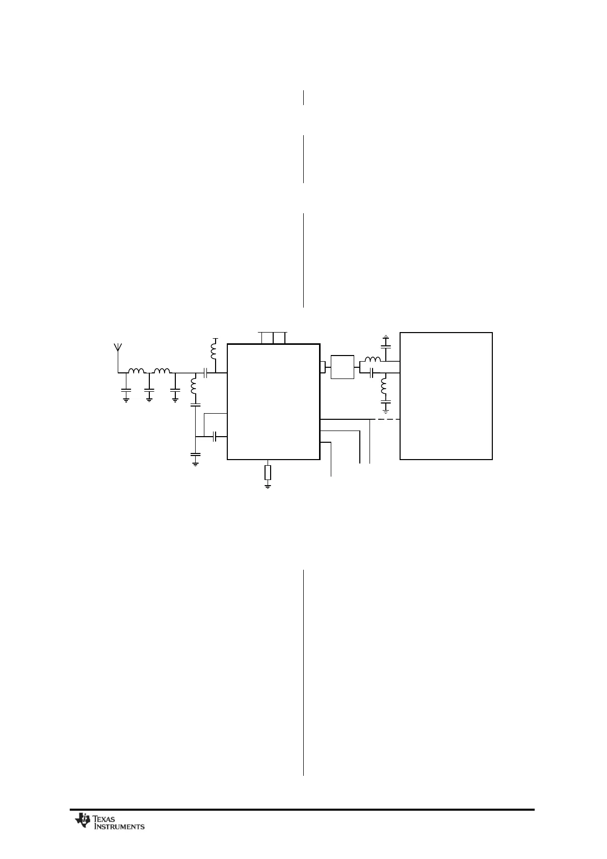
28.8 Increasing Range
In some applications it may be necessary to
extend the range. The
CC1190
[21] is a range
extender for 850-950 MHz RF transceivers,
transmitters, and System-on-Chip devices
from Texas Instruments. It increases the link
budget by providing a power amplifier (PA) for
increased output power, and a low-noise
amplifier (LNA) with low noise figure for
improved receiver sensitivity in addition to
switches and RF matching for simple design of
high performance wireless systems. Refer to
AN094 [22] and AN096 [23] for performance
figures of the
CC1101
+
CC1190
combination.
Figure 33 shows a simplified application
circuit.
Figure 33: Simplified CC1101-CC1190 Application Circuit
29 Configuration Registers
The configuration of
CC1101
is done by
programming 8-bit registers. The optimum
configuration data based on selected system
parameters are most easily found by using the
SmartRF Studio software [5]. Complete
descriptions of the registers are given in the
following tables. After chip reset, all the
registers have default values as shown in the
tables. The optimum register setting might
differ from the default value. After a reset, all
registers that shall be different from the default
value therefore needs to be programmed
through the SPI interface.
There are 13 command strobe registers, listed
in Table 42. Accessing these registers will
initiate the change of an internal state or
mode. There are 47 normal 8-bit configuration
registers listed in Table 43. Many of these
registers are for test purposes only, and need
not be written for normal operation of
CC1101
.
There are also 12 status registers that are
listed in Table 44. These registers, which are
read-only, contain information about the status
of
CC1101
.
The two FIFOs are accessed through one 8-bit
register. Write operations write to the TX FIFO,
while read operations read from the RX FIFO.
During the header byte transfer and while
writing data to a register or the TX FIFO, a
status byte is returned on the SO line. This
status byte is described in Table 23 on page
31.