CC1101
SWRS061H Page 24 of 98
and C101 can be omitted when using a reference signal.
7.5 Additional Filtering
In the 868/915 MHz reference design, C126
and L125 together with C125 build an optional
filter to reduce emission at carrier frequency –
169 MHz. This filter is necessary for
applications with an external antenna
connector that seek compliance with ETSI EN
300-220. For more information, see DN017 [9].
If this filtering is not necessary, C125 will work
as a DC block (only necessary if there is a DC
path in the antenna). C126 and L125 should in
that case be left unmounted.
Additional external components (e.g. an RF
SAW filter) may be used in order to improve
the performance in specific applications.
7.6 Power Supply Decoupling
The power supply must be properly decoupled
close to the supply pins. Note that decoupling
capacitors are not shown in the application
circuit. The placement and the size of the
decoupling capacitors are very important to
achieve the optimum performance. The
CC1101EM reference designs ([1] and [2])
should be followed closely.
7.7 Antenna Considerations
The reference design ([1] and [2]) contains a
SMA connector and is matched for a 50
load. The SMA connector makes it easy to
connect evaluation modules and prototypes to
different test equipment for example a
spectrum analyzer. The SMA connector can
also be replaced by an antenna suitable for
the desired application. Please refer to the
antenna selection guide [13] for further details
regarding antenna solutions provided by TI.
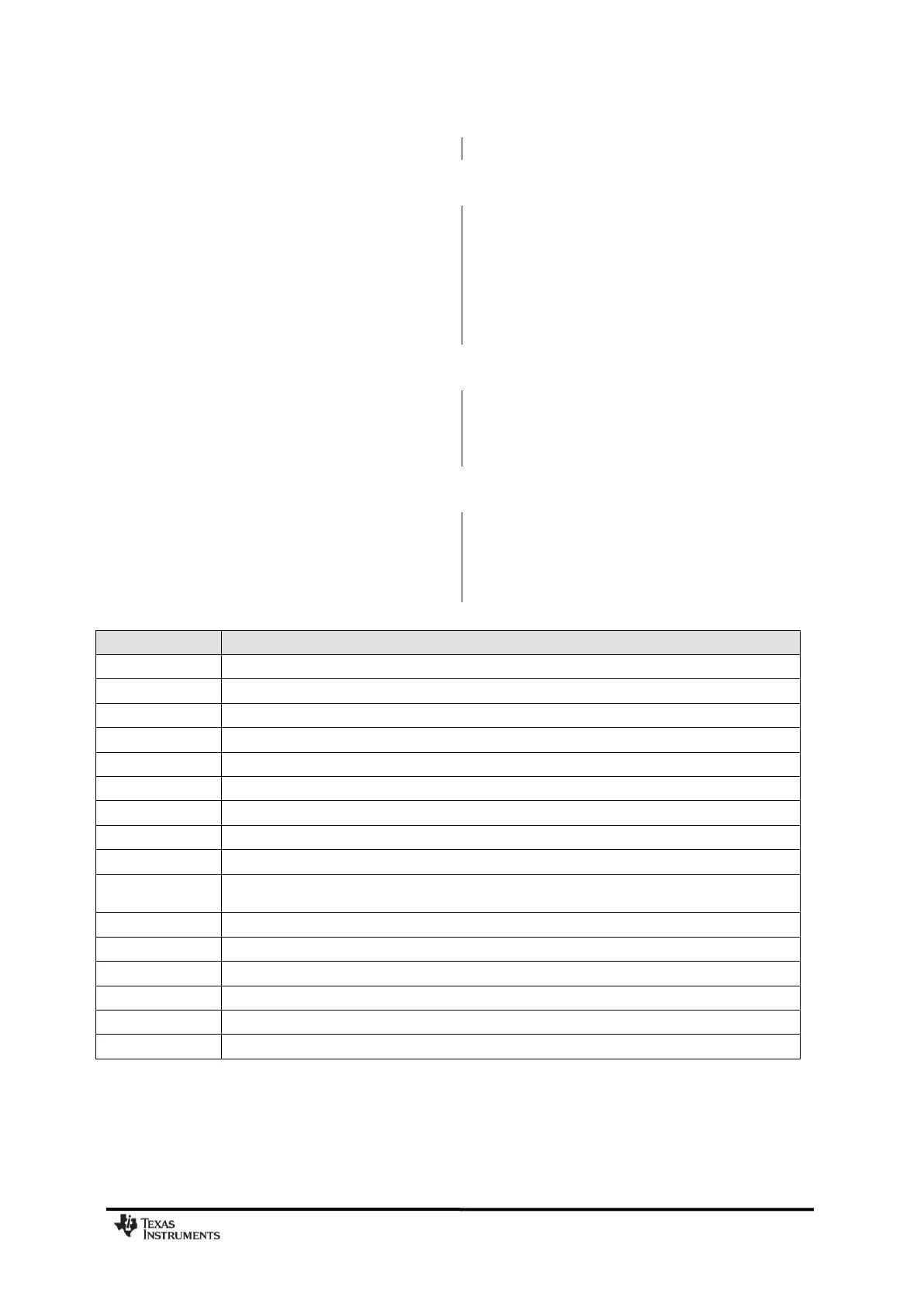
Table 20: Overview of External Components (excluding supply decoupling capacitors)
Decoupling capacitor for on-chip voltage regulator to digital part
Crystal loading capacitors
RF balun/matching capacitors
RF LC filter/matching filter capacitor (315/433 MHz). RF balun/matching capacitor (868/915 MHz).
RF LC filter/matching capacitor
RF balun DC blocking capacitor
RF LC filter DC blocking capacitor and part of optional RF LC filter (868/915 MHz)
Part of optional RF LC filter and DC-block (868/915 MHz)
RF balun/matching inductors (inexpensive multi-layer type)
RF LC filter/matching filter inductor (315 and 433 MHz). RF balun/matching inductor (868/915 MHz).
(inexpensive multi-layer type)
RF LC filter/matching filter inductor (inexpensive multi-layer type)
RF LC filter/matching filter inductor (inexpensive multi-layer type)
Optional RF LC filter/matching filter inductor (inexpensive multi-layer type) (868/915 MHz)
RF balun/matching inductor. (inexpensive multi-layer type)
Resistor for internal bias current reference