CC1101
SWRS061H Page 57 of 98
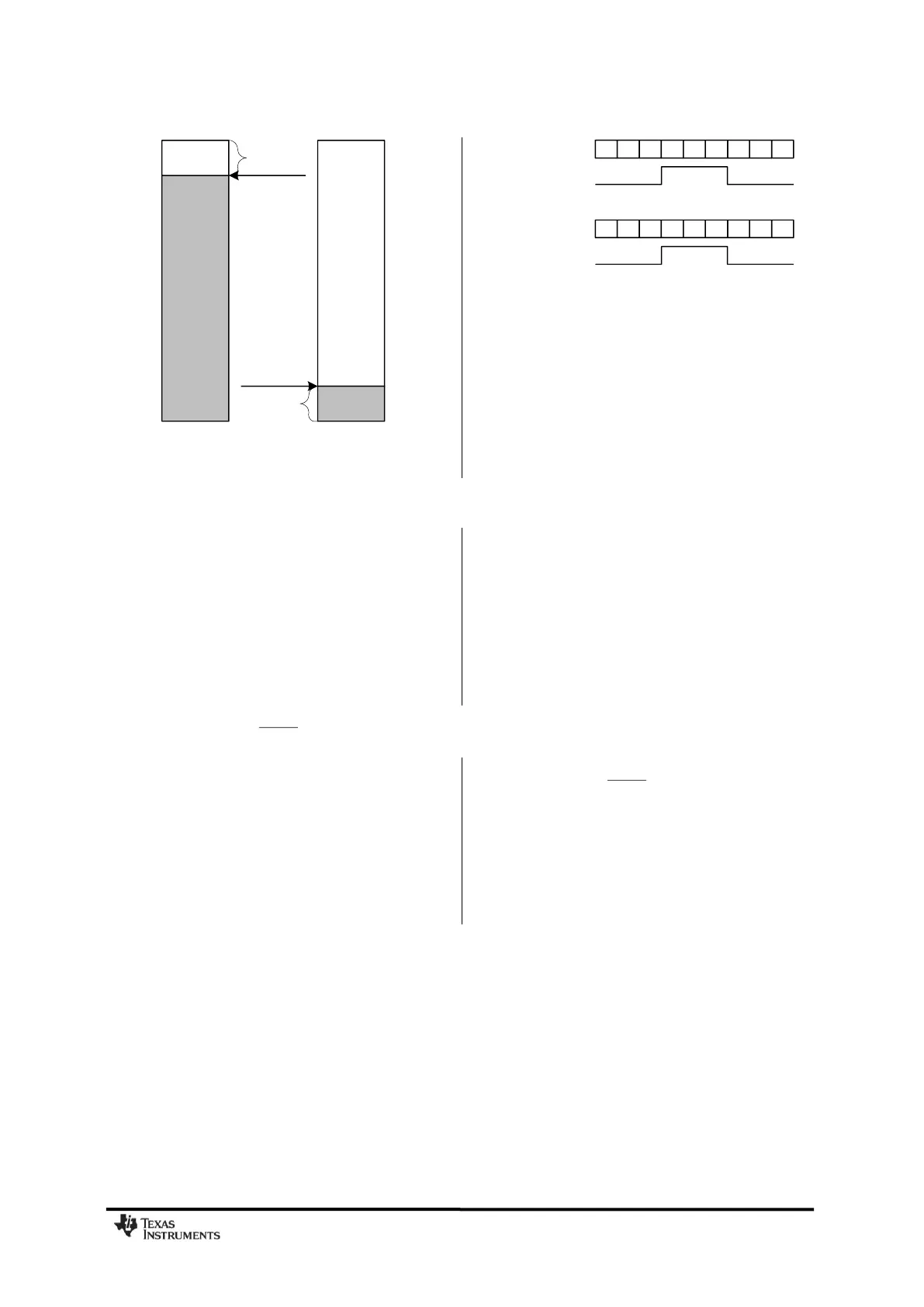
56 bytes
8 bytes
Overflow
margin
Underflow
margin
FIFO_THR=13
FIFO_THR=13
RXFIFO TXFIFO
Figure 29: Example of FIFOs at Threshold
53 54 55 56 5354555657
6 7 8 9 678910
NUM_RXBYTES
GDO
NUM_TXBYTES
GDO
Figure 30: Number of Bytes in FIFO vs. the
GDO Signal (GDOx_CFG=0x00 in RX and
GDOx_CFG=0x02 in TX, FIFO_THR=13)
21 Frequency Programming
The frequency programming in
CC1101
is
designed to minimize the programming
needed in a channel-oriented system.
To set up a system with channel numbers, the
desired channel spacing is programmed with
the MDMCFG0.CHANSPC_M and
MDMCFG1.CHANSPC_E registers. The channel
spacing registers are mantissa and exponent
respectively. The base or start frequency is set
by the 24 bit frequency word located in the
FREQ2, FREQ1, and FREQ0 registers. This
word will typically be set to the centre of the
lowest channel frequency that is to be used.
The desired channel number is programmed
with the 8-bit channel number register,
CHANNR.CHAN, which is multiplied by the
channel offset. The resultant carrier frequency
is given by:
2_
16
2_256
2
ECHANSPC
XOSC
carrier
MCHANSPCCHANFREQ
f
f
With a 26 MHz crystal the maximum channel
spacing is 405 kHz. To get e.g. 1 MHz channel
spacing, one solution is to use 333 kHz
channel spacing and select each third channel
in CHANNR.CHAN.
The preferred IF frequency is programmed
with the FSCTRL1.FREQ_IF register. The IF
frequency is given by:
If any frequency programming register is
altered when the frequency synthesizer is
running, the synthesizer may give an
undesired response. Hence, the frequency
programming should only be updated when
the radio is in the IDLE state.