CC1101
SWRS061H Page 35 of 98
12 Data Rate Programming
The data rate used when transmitting, or the
data rate expected in receive is programmed
by the MDMCFG3.DRATE_M and the
MDMCFG4.DRATE_E configuration registers.
The data rate is given by the formula below.
As the formula shows, the programmed data
rate depends on the crystal frequency.
XOSC
EDRATE
DATA
f
MDRATE
R
28
_
2
2_256
The following approach can be used to find
suitable values for a given data rate:
256
2
2
_
2
log_
_
28
20
2
EDRATE
XOSC
DATA
XOSC
DATA
f
R
MDRAT E
f
R
EDRAT E
If DRATE_M is rounded to the nearest integer
and becomes 256, increment DRATE_E and
use DRATE_M = 0.
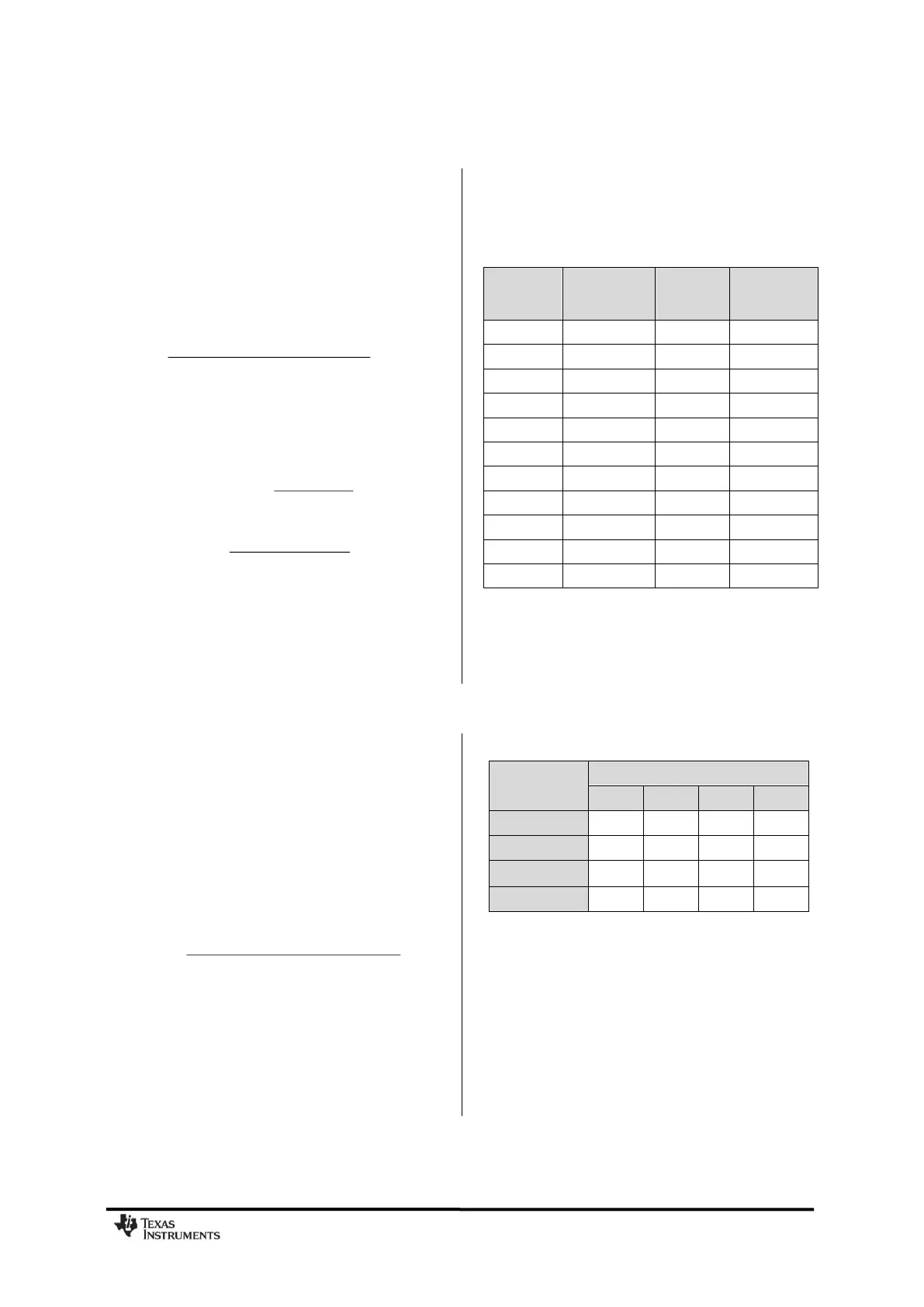
The data rate can be set from 0.6 kBaud to
500 kBaud with the minimum step size
according to Table 25 below. See Table 3 for
the minimum and maximum data rates for the
different modulation formats.
Typical Data
Rate
[kBaud]
Data rate
Step Size
[kBaud]
Table 25: Data Rate Step Size (assuming a
26 MHz crystal)
13 Receiver Channel Filter Bandwidth
In order to meet different channel width
requirements, the receiver channel filter is
programmable. The MDMCFG4.CHANBW_E and
MDMCFG4.CHANBW_M configuration registers
control the receiver channel filter bandwidth,
which scales with the crystal oscillator
frequency.
The following formula gives the relation
between the register settings and the channel
filter bandwidth:
ECHANBW
XOSC
channel
MCHANBW
f
BW
_
2)·_4(8
Table 26 lists the channel filter bandwidths
supported by the
CC1101
.
Table 26: Channel Filter Bandwidths [kHz]
(assuming a 26 MHz crystal)
By compensating for a frequency offset
between the transmitter and the receiver, the
filter bandwidth can be reduced and the
sensitivity improved, see more in DN005 [17]
and in Section 14.1.