CC1101
SWRS061H Page 56 of 98
20 Data FIFO
The
CC1101
contains two 64 byte FIFOs, one
for received data and one for data to be
transmitted. The SPI interface is used to read
from the RX FIFO and write to the TX FIFO.
Section 10.5 contains details on the SPI FIFO
access. The FIFO controller will detect
overflow in the RX FIFO and underflow in the
TX FIFO.
When writing to the TX FIFO it is the
responsibility of the MCU to avoid TX FIFO
overflow. A TX FIFO overflow will result in an
error in the TX FIFO content.
Likewise, when reading the RX FIFO the MCU
must avoid reading the RX FIFO past its empty
value since a RX FIFO underflow will result in
an error in the data read out of the RX FIFO.
The chip status byte that is available on the
SO pin while transferring the SPI header and
contains the fill grade of the RX FIFO if the
access is a read operation and the fill grade of
the TX FIFO if the access is a write operation.
Section 10.1 contains more details on this.
The number of bytes in the RX FIFO and TX
FIFO can be read from the status registers
RXBYTES.NUM_RXBYTES and
TXBYTES.NUM_TXBYTES respectively. If a
received data byte is written to the RX FIFO at
the exact same time as the last byte in the RX
FIFO is read over the SPI interface, the RX
FIFO pointer is not properly updated and the
last read byte will be duplicated. To avoid this
problem, the RX FIFO should never be
emptied before the last byte of the packet is
received.
For packet lengths less than 64 bytes it is
recommended to wait until the complete
packet has been received before reading it out
of the RX FIFO.
If the packet length is larger than 64 bytes, the
MCU must determine how many bytes can be
read from the RX FIFO
(RXBYTES.NUM_RXBYTES-1). The following
software routine can be used:
1. Read RXBYTES.NUM_RXBYTES
repeatedly at a rate specified to be at least
twice that of which RF bytes are received
until the same value is returned twice;
store value in n.
2. If n < # of bytes remaining in packet, read
n-1 bytes from the RX FIFO.
3. Repeat steps 1 and 2 until n = # of bytes
remaining in packet.
4. Read the remaining bytes from the RX
FIFO.
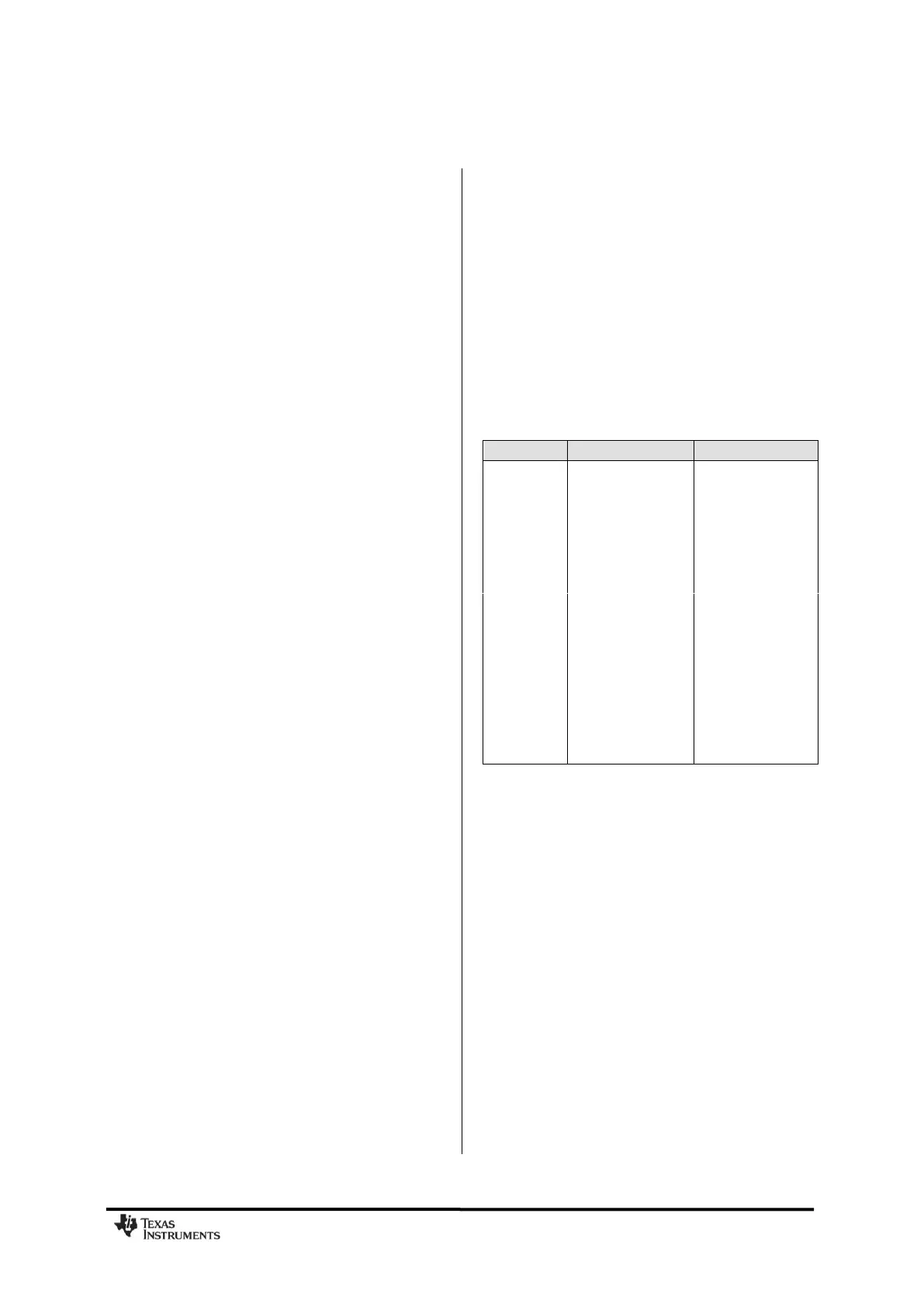
The 4-bit FIFOTHR.FIFO_THR setting is used
to program threshold points in the FIFOs.
Table 36 lists the 16 FIFO_THR settings and
the corresponding thresholds for the RX and
TX FIFOs. The threshold value is coded in
opposite directions for the RX FIFO and TX
FIFO. This gives equal margin to the overflow
and underflow conditions when the threshold
is reached.
Table 36: FIFO_THR Settings and the
Corresponding FIFO Thresholds
A signal will assert when the number of bytes
in the FIFO is equal to or higher than the
programmed threshold. This signal can be
viewed on the GDO pins (see Table 41 on
page 62).
Figure 29 shows the number of bytes in both
the RX FIFO and TX FIFO when the threshold
signal toggles in the case of FIFO_THR=13.
Figure 30 shows the signal on the GDO pin as
the respective FIFO is filled above the
threshold, and then drained below in the case
of FIFO_THR=13.