CC1101
SWRS061H Page 19 of 98
4.6 Frequency Synthesizer Characteristics
T
A
= 25C, VDD = 3.0 V if nothing else is stated. All measurement results are obtained using the CC1101EM reference designs
([1] and [2]). Min figures are given using a 27 MHz crystal. Typ and max figures are given using a 26 MHz crystal.
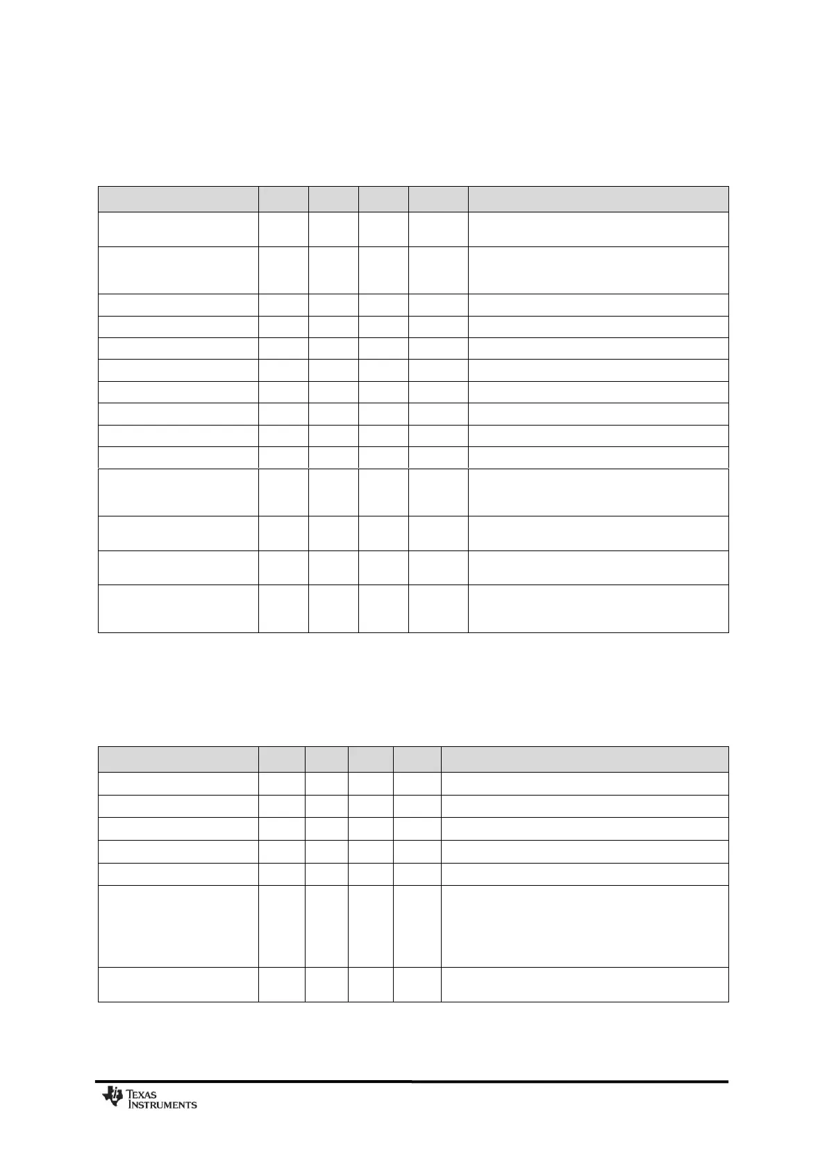
Table 15: Frequency Synthesizer Parameters
4.7 Analog Temperature Sensor
T
A
= 25C, VDD = 3.0 V if nothing else is stated. All measurement results obtained using the CC1101EM reference designs ([1]
and [2]). Note that it is necessary to write 0xBF to the PTEST register to use the analog temperature sensor in the IDLE state.
Table 16: Analog Temperature Sensor Parameters
Programmed frequency
resolution
26-27 MHz crystal. The resolution (in Hz) is equal
for all frequency bands
Synthesizer frequency
tolerance
Given by crystal used. Required accuracy
(including temperature and aging) depends on
frequency band and channel bandwidth / spacing
@ 50 kHz offset from carrier
@ 100 kHz offset from carrier
@ 200 kHz offset from carrier
@ 500 kHz offset from carrier
@ 1 MHz offset from carrier
@ 2 MHz offset from carrier
@ 5 MHz offset from carrier
@ 10 MHz offset from carrier
PLL turn-on / hop time
( See Table 34)
Time from leaving the IDLE state until arriving in
the RX, FSTXON or TX state, when not
performing calibration. Crystal oscillator running.
PLL RX/TX settling time
( See Table 34)
Settling time for the 1·IF frequency step from RX
to TX
PLL TX/RX settling time
( See Table 34)
Settling time for the 1·IF frequency step from TX
to RX. 250 kbps data rate.
PLL calibration time
(See Table 35)
Calibration can be initiated manually or
automatically before entering or after leaving
RX/TX
Fitted from –20 C to +80 C
Error in calculated
temperature, calibrated
From –20 C to +80 C when using 2.47 mV / C, after
1-point calibration at room temperature
*
The indicated minimum and maximum error with 1-
point calibration is based on simulated values for
typical process parameters
Current consumption
increase when enabled