CC1101
SWRS061H Page 42 of 98
MISO line each time a header byte, data byte,
or command strobe is sent on the SPI bus.
It is recommended to employ an interrupt
driven solution since high rate SPI polling
reduces the RX sensitivity. Furthermore, as
explained in Section 10.3 and the
CC1101
Errata Notes [3], when using SPI polling, there
is a small, but finite, probability that a single
read from registers PKTSTATUS , RXBYTES
and TXBYTES is being corrupt. The same is
the case when reading the chip status byte.
Refer to the TI website for SW examples ([6]
and [7]).
16 Modulation Formats
CC1101
supports amplitude, frequency, and
phase shift modulation formats. The desired
modulation format is set in the
MDMCFG2.MOD_FORMAT register.
Optionally, the data stream can be Manchester
coded by the modulator and decoded by the
demodulator. This option is enabled by setting
MDMCFG2.MANCHESTER_EN=1.
16.1 Frequency Shift Keying
CC1101
supports both 2-FSK and 4-FSK
modulation. 2-FSK can optionally be shaped
by a Gaussian filter with BT = 0.5, producing a
GFSK modulated signal. This spectrum-
shaping feature improves adjacent channel
power (ACP) and occupied bandwidth. When
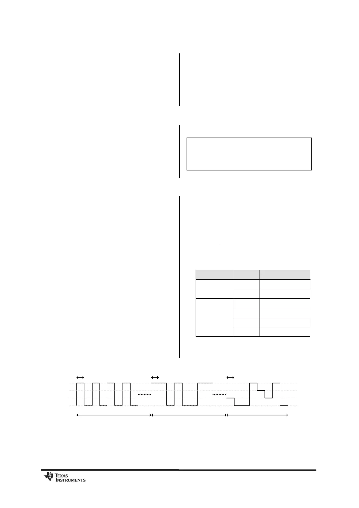
selecting 4-FSK, the preamble and sync word
is sent using 2-FSK (see Figure 21).
In „true‟ 2-FSK systems with abrupt frequency
shifting, the spectrum is inherently broad. By
making the frequency shift „softer‟, the
spectrum can be made significantly narrower.
Thus, higher data rates can be transmitted in
the same bandwidth using GFSK.
When 2-FSK/GFSK/4-FSK modulation is used,
the DEVIATN register specifies the expected
frequency deviation of incoming signals in RX
and should be the same as the TX deviation
for demodulation to be performed reliably and
robustly.
The frequency deviation is programmed with
the DEVIATION_M and DEVIATION_E values
in the DEVIATN register. The value has an
exponent/mantissa form, and the resultant
deviation is given by:
EDEVIATION
xosc
dev
MDEVIATION
f
f
_
17
2)_8(
2
The symbol encoding is shown in Table 29.
Table 29: Symbol Encoding for 2-FSK/GFSK
and 4-FSK Modulation
+1
+1/3
-1/3
-1
1 0 1 0 1 0 1 0 1 1 0 1 0 0 1 1 00 01 01 11 10 00 11 01
Preamble
0xAA
Sync
0xD3
Data
0x17 0x8D
1/Baud Rate 1/Baud Rate 1/Baud Rate
Figure 21: Data Sent Over the Air (MDMCFG2.MOD_FORMAT=100)
Note: Manchester encoding is not
supported at the same time as using the
FEC/Interleaver option or when using MSK
and 4-FSK modulation.