CC1101
SWRS061H Page 26 of 98
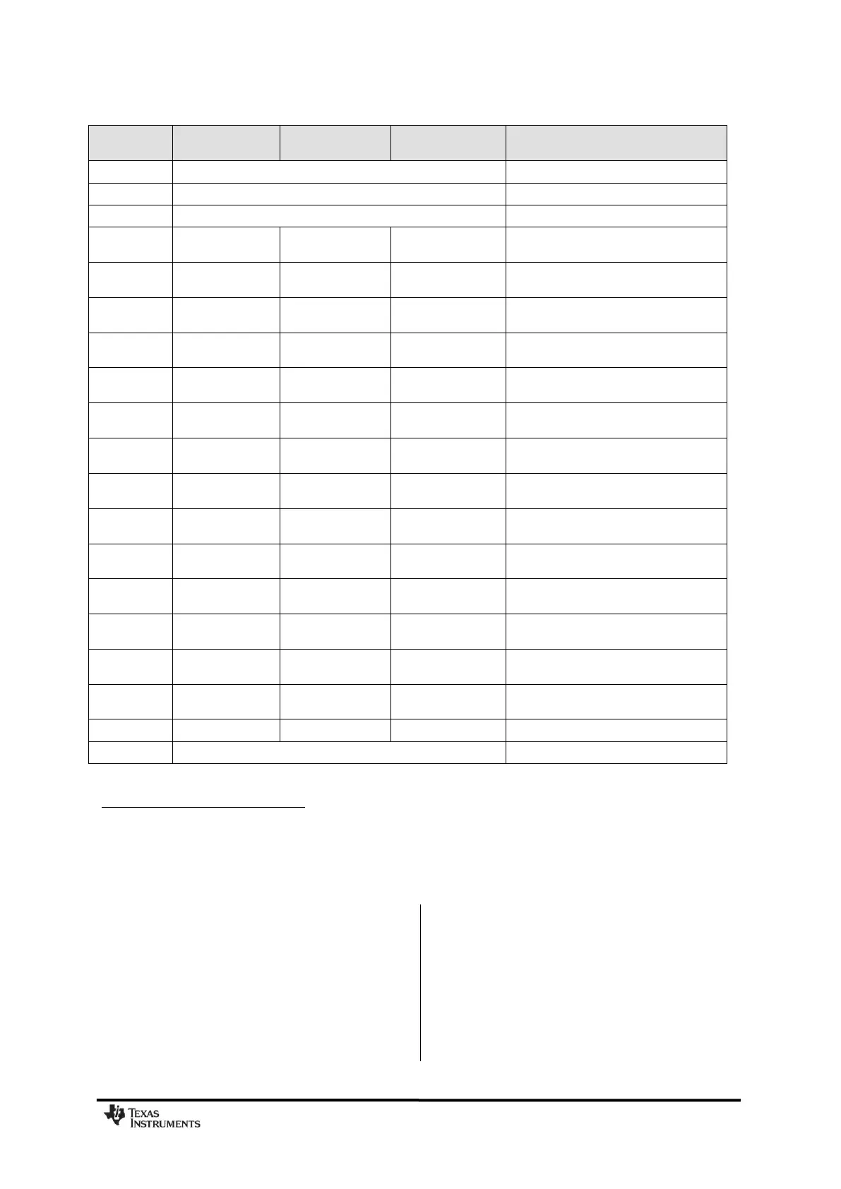
Table 21: Bill Of Materials for the Application Circuit
Refer to design note DN032 [24] for information about performance when using inductors from
other vendors than Murata.
7.8 PCB Layout Recommendations
The top layer should be used for signal
routing, and the open areas should be filled
with metallization connected to ground using
several vias.
The area under the chip is used for grounding
and shall be connected to the bottom ground
plane with several vias for good thermal
performance and sufficiently low inductance to
ground.
In the CC1101EM reference designs ([1] and
[2]), 5 vias are placed inside the exposed die
attached pad. These vias should be “tented”
(covered with solder mask) on the component
side of the PCB to avoid migration of solder
through the vias during the solder reflow
process.
The solder paste coverage should not be
100%. If it is, out gassing may occur during the
6.8 pF ± 0.5 pF,
0402 NP0
3.9 pF ± 0.25 pF,
0402 NP0
1.0 pF ± 0.25 pF,
0402 NP0
8.2 pF ± 0.5 pF,
0402 NP0
1.5 pF ± 0.25 pF,
0402 NP0
6.8 pF ± 0.5 pF,
0402 NP0
5.6 pF ± 0.5 pF,
0402 NP0
3.3 pF ± 0.25 pF,
0402 NP0
6.8 pF ± 0.5 pF,
0402 NP0
3.9 pF ± 0.25 pF,
0402 NP0
1.5 pF ± 0.25 pF,
0402 NP0
33 nH ± 5%, 0402
monolithic
27 nH ± 5%, 0402
monolithic
12 nH ± 5%, 0402
monolithic
Murata LQG15HS series (315/433 MHz)
Murata LQW15xx series (868/915 MHz)
18 nH ± 5%, 0402
monolithic
22 nH ± 5%, 0402
monolithic
18 nH ± 5%, 0402
monolithic
Murata LQG15HS series (315/433 MHz)
Murata LQW15xx series (868/915 MHz)
33 nH ± 5%, 0402
monolithic
27 nH ± 5%, 0402
monolithic
12 nH ± 5%, 0402
monolithic
Murata LQG15HS series (315/433 MHz)
Murata LQW15xx series (868/915 MHz)
12 nH ± 5%, 0402
monolithic
Murata LQG15HS series (315/433 MHz)
Murata LQW15xx series (868/915 MHz)
3.3 nH ± 5%, 0402
monolithic
Murata LQG15HS series (315/433 MHz)
Murata LQW15xx series (868/915 MHz)
33 nH ± 5%, 0402
monolithic
27 nH ± 5%, 0402
monolithic
12 nH ± 5%, 0402
monolithic
Murata LQG15HS series (315/433 MHz)
Murata LQW15xx series (868/915 MHz)
18 nH ± 5%, 0402
monolithic
Murata LQG15HS series (315/433 MHz)
Murata LQW15xx series (868/915 MHz)
26.0 MHz surface mount crystal
NDK, NX3225GA or AT-41CD2