Hot plug: The PRSNT1# and PRSNT2# signals are the hot plug presence detect signals. The PRSNT1# is
pulled up and PRSNT2# is connected to GPIO expander, so that PRSNT1# will be pulled low when a add on
card is plugged in as both the PRSNT signals in add on cards will be shorted. Optional resistor is provided to
short the PRSNT1# and PRSNT2# to support host and device mode.
For choosing Host or device operation of PCIe card, following resistors must be mounted/unmounted as
mentioned in Table 4-15.
Table 4-15. Resistors for Selecting PCIe Card Host or Device Operation
Mode Mount Demount
Host mode R674 R675
R679
Device mode R675 R674
R679
Additional Options:
Optional MDIO bus and USB2.0 interface is supported for external PCIe add on cards.
SoC Main domain (CPSW9G0) MDIO signals are interfaced to the x1L PCIe Socket (J11) through 0-Ω inline
resistors (R137 and R136) when network (Ethernet) based add on cards inserted into J11. The path is
disconnected by default.
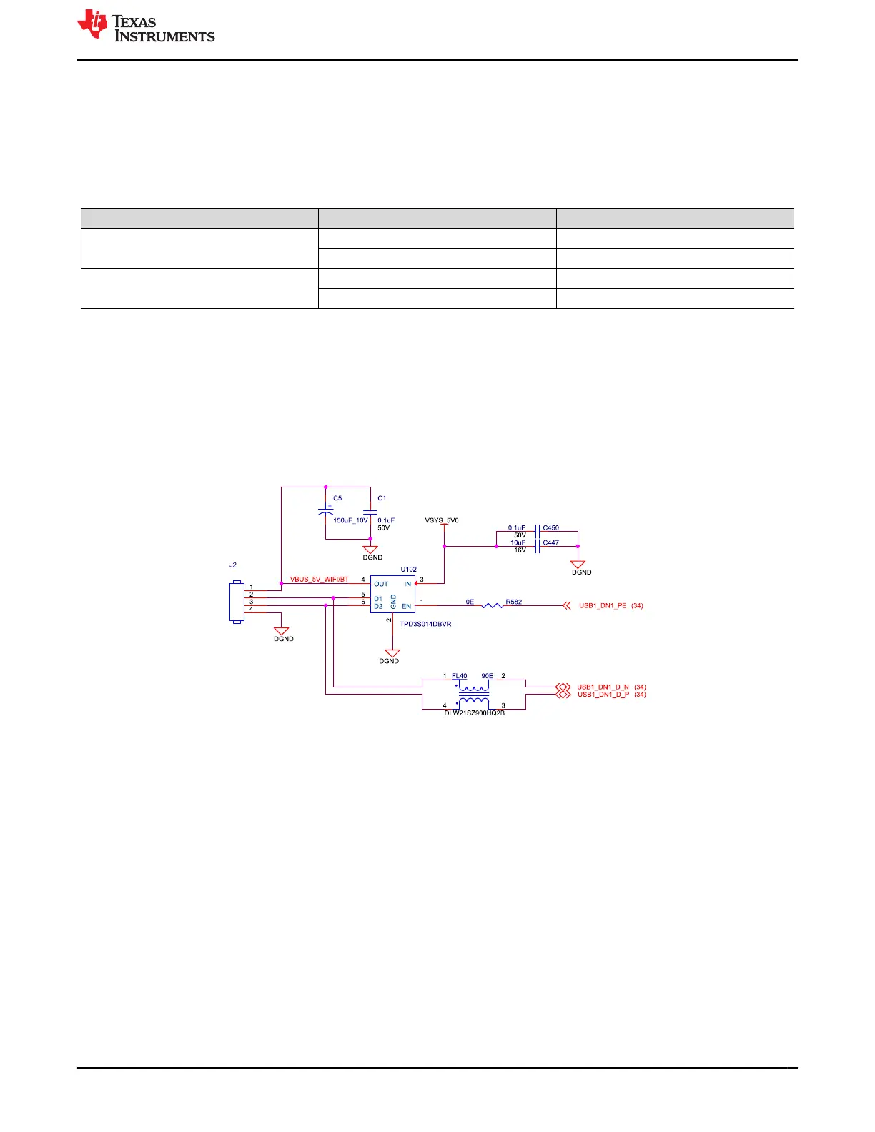
Also, USB2.0 data signals from USB HUB downstream port is interfaced to 4 pin header (J2) and the 5 V supply
is provided through the load switch.
Figure 4-22. USB2.0 Header Connection
www.ti.com J721E EVM Hardware Architecture
SPRUIS4D – MAY 2020 – REVISED MARCH 2022
Submit Document Feedback
Jacinto7 J721E/DRA829/TDA4VM Evaluation Module (EVM) 55
Copyright © 2022 Texas Instruments Incorporated