4.8.4 MMC Interface
The processor supports two MMC (MMC0 and 1) ports. MMC0 is connected to eMMC flash and MMC1 is
interfaced with Micro SD Socket on the Common processor board.
4.8.4.1 MMC0 - eMMC Interface
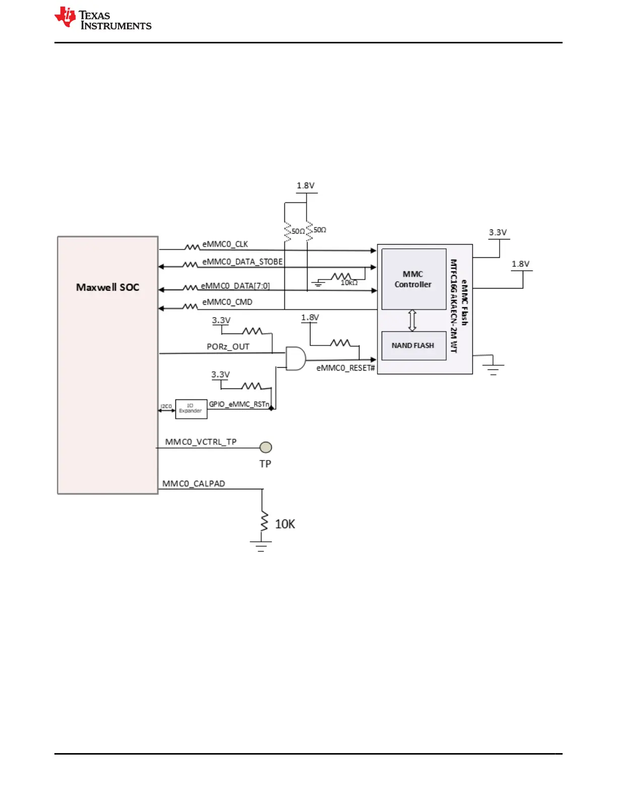
A 16GB, V5.1 compliant eMMC flash memory Mfr. Part# MTFC16GAPALBH-AAT ES is interfaced to MMC0 port
of the J721E SoC. The flash is connected to 8 bits of the MMC0 interface supporting HS400 double data rates
up to 200 MHz. External pull up resistors 49.9K are provided on DATA [7:0], CMD and Reset signals, pull down
resistor is provided on the data strobe signal to prevent bus floating.
Figure 4-13. eMMC Memory Block Diagram
www.ti.com J721E EVM Hardware Architecture
SPRUIS4D – MAY 2020 – REVISED MARCH 2022
Submit Document Feedback
Jacinto7 J721E/DRA829/TDA4VM Evaluation Module (EVM) 45
Copyright © 2022 Texas Instruments Incorporated