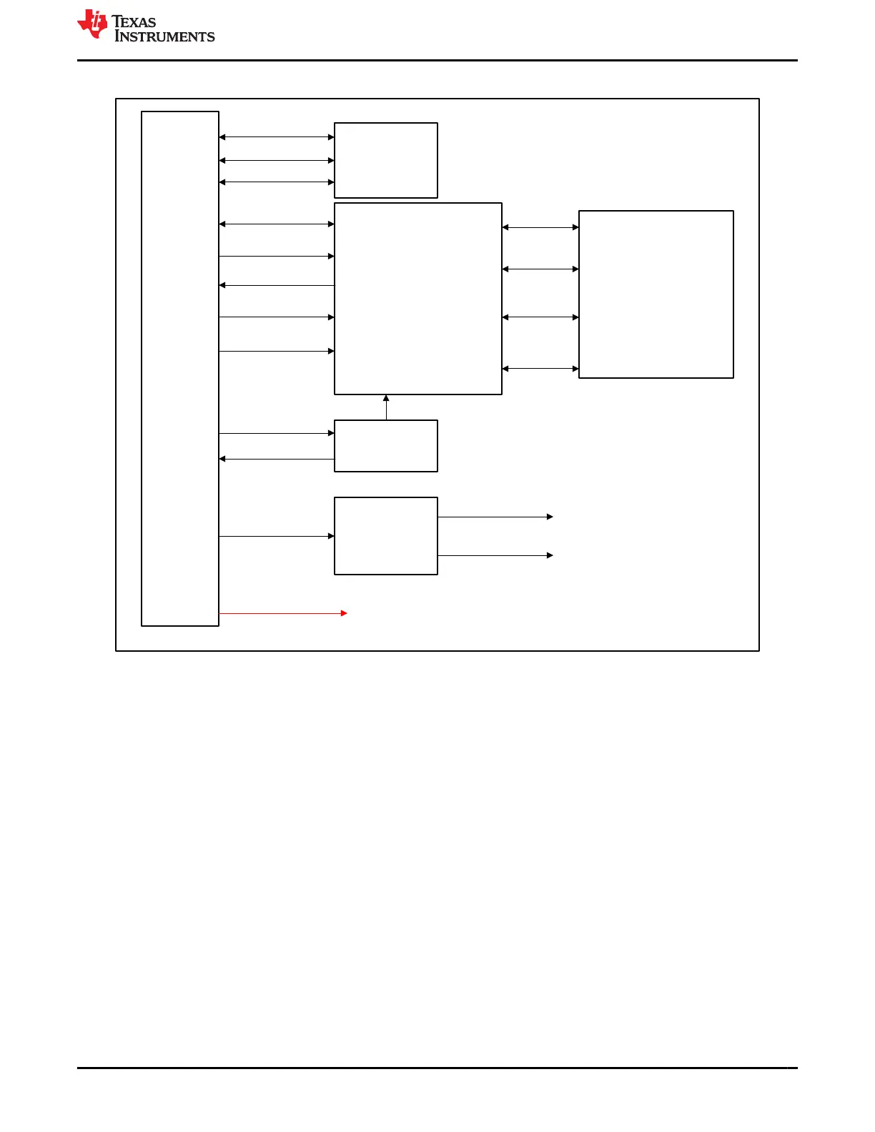
Figure 4-2 shows the Quad Port Ethernet Expansion Board functional block diagram.
ENET EXPANSION COLLETOR
[171450-3106]
WKUP_I2C0
EEPROM_A0,A1,A2
EEPROM_WP
EEPROM
[CAT24C256]
QSGMII PHY
(VSC8514XMK-11)
QSGMII4
REFCLK
MDIO
MDC
RSTn,INTn&
POWEROWN
Clock
Generator
CDCI6214
I2C0_SCL
I2C0_SDA
VOLTAGE
REGULATOR
TPS74801
(x2)
3.3 V
2.5 V
1 V
POWER(12 V, 5 V, 3V3)
STACKED RJ45
WITH INTEGRATED
MAGNETICS
(X2)
LPJG17512AONL
Port 1
Port 2
Port 3
Port 4
Figure 4-2. Quad Port Ethernet Expansion Functional Block diagram
www.ti.com J721E EVM Hardware Architecture
SPRUIS4D – MAY 2020 – REVISED MARCH 2022
Submit Document Feedback
Jacinto7 J721E/DRA829/TDA4VM Evaluation Module (EVM) 27
Copyright © 2022 Texas Instruments Incorporated