3.2.2 Power Regulators and Power Status LEDs
The processor Card utilizes an array of DC-DC converters to supply the various memories, clocks and other
components on the Card with the necessary voltage and the power required.
Dual Buck controller LM5140-Q1 provides the primary stage power conversion (12 V to 5 V / 3.3 V). These 3.3 V
and 5 V is the primary voltages for the SoM power management resources.
Buck-Boost controller LM5175 and another Buck controller LM5141 provides 12 V and 3.3 V supplies to the
expansion connectors. The power good signals of these power regulators are used to generate the SoC PORz.
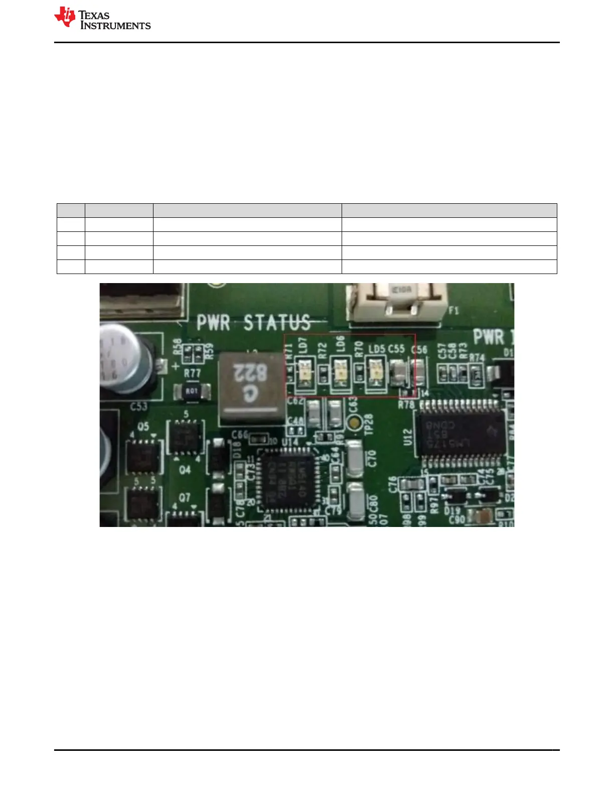
Multiple power-indication LEDs are provided on board to give users positive confirmation of the status of output
of major supplies. The LEDs indicated power in the various domains.
Table 3-3. Power LEDs
Sl No LED Power Status Sch Net Name
1 LD2 Input Power On/Off VINPUT
2 LD7 Regulated Power On/Off VSYS_3V3
3 LD5 SoC Main Domain On/Off VSYS_IO_3V3
4 LD6 SoC MCU Domain On/Off VSYS_MCUIO_3V3
Figure 3-4. Power Status LEDs
www.ti.com EVM User Setup/Configuration
SPRUIS4D – MAY 2020 – REVISED MARCH 2022
Submit Document Feedback
Jacinto7 J721E/DRA829/TDA4VM Evaluation Module (EVM) 15
Copyright © 2022 Texas Instruments Incorporated