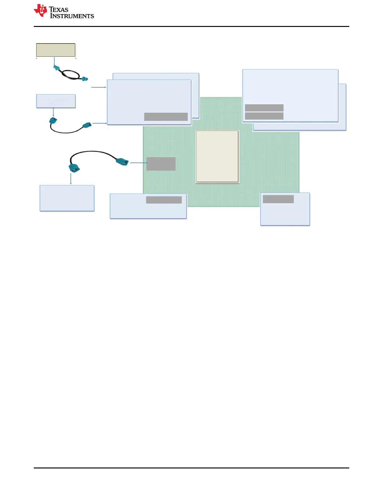
Figure 2-2 shows the overall architecture of the J721E EVM.
J721E SOM
Common Processor Board
Gateway/Ethernet Switch/Industrial Expansion Board 1
MIPI 60 pin
JTAG Adapter Board - cTI 14 pin and 20pin
CSI2 Expansion
Expansion
FPD LINK IV
Display
Display Adapter Board
with Display Panel
ENET Expansion
Quad Port Ethernet Board
Infotainment Expansion Board
2
Fusion2 Serial Capture Board 2
Single Link
Radar Interconnect
Camera Module
with serializer
Expansion
Fusion1 Serial Capture Board
1
A. Only one board can be connected to Expansion connector at a time.
B. Only one board can be connected to CSI2 Expansion connector at a time.
Figure 2-2. System Architecture Interface
The J721E EVM System on Module (SoM) board, a Jacinto7 Common Processor board, and Quad-Port
Ethernet Board. Detailed descriptions of these cards are explained in the following sections.
www.ti.com J721E EVM Overview
SPRUIS4D – MAY 2020 – REVISED MARCH 2022
Submit Document Feedback
Jacinto7 J721E/DRA829/TDA4VM Evaluation Module (EVM) 7
Copyright © 2022 Texas Instruments Incorporated